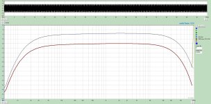
Yes,Mister Audio,
At mid frequencies . . .
Connecting an 8 Ohm speaker to a:
6.4k to 8 Ohm transformer
versus to a 3.2k to 4 Ohm transformer . . .
Will have the same power to the speaker.
The simple point I made was regarding the damping factor which specifically effects low frequencies.
My point was based on a scenario where primary conditions are optimal, and you have the choice of
both a 4 ohm & 8 ohm tap > meaning using the 4 ohm tap will provide a higher damping factor
at the expense of reduced voltage output.
( I do understand that a function of transformers is 'reflected impedance' )
I do intend to order the bypass caps along with the bias resistors mentioned in the design for the various output tubes that have been tried with it. I do agree that the proper way to compare two designs, is by implementing both and comparing the results; I may go down that road if cost and time restrictions permit it. I don't expect the simulations to accurately match reality (in fact I do get suspiciously low THD values), but they're useful in studying the circuit without having to order parts and desolder and resolder components etc. (and without unnecessarily exposing yourself to high voltages).The only way to determine what your changes will sound like is to build both "designs" and listen to the differences. Things like removing the cathode bypass cap doesn't just impact gain, that can change the whole sound signature of an amp. If I have learned anything, dwelling on theory will only get you so far. Many times what something should do, even on computer simulations and applying information from the data sheets, might not happen in the actual built amp.
I have already done that. Still waiting for their reply.As far as your transformer question, I would be asking this question to the folks who make transformers.
Imagine you have 2 transformers of the same size, for the same output power.
Right, so since higher loads are meant to be driven at higher voltages, the currents will be lower for the same output power so the wiring can be made accordingly finer and the windings can change substantially. This means you can get either a higher inductance, or perhaps a similar inductance at the now lower excitation current. You also get different DC resistances. I have asked the manufacturer for specs on the custom wound version. Now I know a bit more about what to look for in interpreting them. I'll post them here when I get them. Thanks for the explanations!How about that?
This is my first amplifier build. I don't have a bin of spare parts or much experience with measurements etc. I do intend to measure and compare what I can (although I probably won't buy two types of OPTs for that purpose; it would certainly be instructive, but also expensive), but I'm still in the research phase trying to figure out what parts to use for the first iteration.I thought that while we were discussing it back and forth you had plenty of time to breadboard and check for yourself.
Sometimes I feel like asking a company that manufactures Hi Fi parts, for extra details about their products . . .
Is a little like asking Coca Cola for the ingredients of their secret formula.
I am not holding my breath waiting for fine details about most manufacturer's output transformers.
Is a little like asking Coca Cola for the ingredients of their secret formula.
I am not holding my breath waiting for fine details about most manufacturer's output transformers.
