If you give your OPA549 more than +/- 30 volts, it will be destroyed.
Bridging is the trick to use: http://sound.westhost.com/bridging.htm
Bridging is the trick to use: http://sound.westhost.com/bridging.htm
demogorgon said:how about runing one chip on +60v and a nother at -60v, and running them as bridged?
just a quick thought from the top of my head..
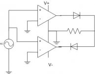
not bridged, parallel... I had an idea like this more than once. Probably need diodes in the output of each amp to prevent them from driving eachother... also would have to deal with crossover distortion.
azira said:
not bridged, parallel... I had an idea like this more than once. Probably need diodes in the output of each amp to prevent them from driving eachother... also would have to deal with crossover distortion.
As Loong said: you can see the AN-1192 App Note for some detail.
It has been discussed, builded and tested through people from this forum...and...you can find AN-1192 at the website of national, I think it is www.national.com
ErikdeBest said:
As Loong said: you can see the AN-1192 App Note for some detail.
It has been discussed, builded and tested through people from this forum...and...you can find AN-1192 at the website of national, I think it is www.national.com
AN-1192 isn't going to help much is this situation.
yes, repeating a ref to something without stating that it had no new info beyond how to bridge was annoying
but http://www.edn.com/contents/images/45890.pdf might help
"Bootstrapping your op amp yields wide voltage swings" shows how to use transistors to increase V handling
but http://www.edn.com/contents/images/45890.pdf might help
"Bootstrapping your op amp yields wide voltage swings" shows how to use transistors to increase V handling
soundNERD said:would this work?
As a voicecoil burner, it would be great. As an amplifier, nope. See my last
")
richie00boy said:
As a voicecoil burner, it would be great. As an amplifier, nope. See my last
I think you are assuming that each chip's quiescent output is centered on it's rails and not at GND.
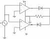
This kind of what you were thinking soundNERD? I scribbled this down a while ago, still a lot of hurdles to clear before it'd be a usable idea though..
good part is that the chip wouldn't have to swing rail to rail, infact only being able to get within .7V of the rail would be ideal.
edit: I remember now, after posting why I scrapped this idea... diodes still don't isolate the outputs from driving eachother... damn...
good part is that the chip wouldn't have to swing rail to rail, infact only being able to get within .7V of the rail would be ideal.
edit: I remember now, after posting why I scrapped this idea... diodes still don't isolate the outputs from driving eachother... damn...
Attachments
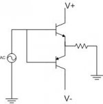
soundNERD said:i think it was something like this: sorry about the schematic i don't have schematic programs installed on this computer. would this work?
Sound heard if this is built.
BANG! Whats that smell?
Source of smell, Speaker, smoke from chip amps, any resistors connected to the circuit, power supply transformer if your not fast or the fuse didn't save you.
This is a bad idea, sorry.
BZ
HDTVman said:
This is a bad idea, sorry.
BZ
Can you explain what is bad about it. It's not down on paper will all values listed... but is the idea really faulty? Is this circuit also a bad idea, it seems like sort of the same thing to me.
--
Danny
Attachments
- Status
- This old topic is closed. If you want to reopen this topic, contact a moderator using the "Report Post" button.
- Home
- Amplifiers
- Chip Amps
- Using 2 chips to boost voltage handling