well i finnaly got my ushio bulb .. and hps ballast i got from ebay like alot of others did ... now i got the wireing diagram but im still not getting it entirelly so is there anyone with the ushio and that cheap hps ballast off of ebay that has pics and a explanation of how to wire it ? i thought superdave had the same setup but cant seem to find the thread that he had about it any help would be great thanks 🙂
P.S diy pj's are far from dead
P.S diy pj's are far from dead
wiring the ballast
Is it a Westrim Products 38121 HID HPS 400W?
That's what mine says on the box, and it came with a wiring page inside. If you have that piece of paper, then use the wiring diagram on the right that includes an ignitor.
****Very important: IF YOU HAVE A DIFFERENT BALLAST, THEN NONE OF THE FOLLOWING APPLIES!!! Ballasts have to be wired according to their manufacturer wiring diagram.****
My wires all had labels printed on them and some were color-coded with heat-shrink tubing.
One end of the lamp is connected to the red ignitor wire that says 'lamp" and the red-tagged ballast wire that says "lamp".
The blue ignitor wire that says "X3" is connected to the blue-tagged ballast wire that says "X3".
The two yellow-tagged ballast wires with push-on connecters connect to the capacitor (one per terminal).
One "COM" wire from the ballast connects to the other end of the lamp and the white "COM" ignitor wire.
The other "COM" wire from the ballast connects to the neutral side of the AC power (typically the white wire in a line cord).
Then you pick one of the four input tap wires to connect to the hot side (black wire) of your AC power (probably through a switch). I used the "120" wire, since I have 120 VAC power. If you have 240 VAC, then pick the "240" wire, etc.
If your line cord has a ground (usually green), then connect that to the bolts you use to mount the capacitor and ballast frame. If if you put all the lamp wiring, ballast, and ignitor inside a metal box, then you should also connect the ground wire to that box.
That's it. Make sure you have a cooling fan that will carry heat away from the area around the lamp. Otherwise it will get stuff hot enough to scorch wood and melt plastic, not to mention destroy your LCD. The first time you fire it up, it will burn a bit funny for a few minutes as some chemical processes take place inside the new lamp. If you turn it off, leave it off for at least 5 minutes before restarting. WEAR UV EYE PROTECTION if you will be exposed directly to the lamp.
If this is not clear enough for you then you should find some handyman, electronics tech, electrician, etc. who can wire it for you. Give him or her the paper sheet that came with the ballast and this post.
ok well here is some pics of the wireing diagram and the ballast cap and coil.
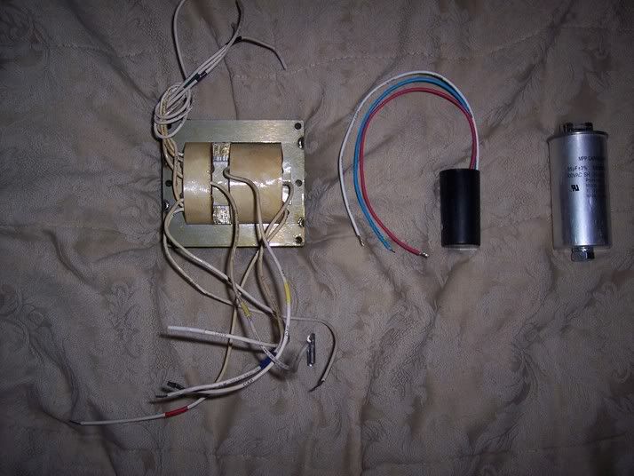
ok i get what wires i need from the ballast
what i dont get is where im supposed to put the coil and cap the cap is the silver metal round thing ......and the coil im guessing is the other black thing that sasy "cd-14" on it not cd-15 ... so yea.
An externally hosted image should be here but it was not working when we last tested it.
An externally hosted image should be here but it was not working when we last tested it.
An externally hosted image should be here but it was not working when we last tested it.
An externally hosted image should be here but it was not working when we last tested it.
An externally hosted image should be here but it was not working when we last tested it.
ok i get what wires i need from the ballast
what i dont get is where im supposed to put the coil and cap the cap is the silver metal round thing ......and the coil im guessing is the other black thing that sasy "cd-14" on it not cd-15 ... so yea.
right so far
Use the last diagram, and don't worry about the ground connection from the ignitor. It doesn't have one.
The ignitor has red, blue, and white wires. The blue wire has printing on it that says "x3". That wire gets connected to the ballast wire with the blue marker (and that wire also says "x3" on it).
The red ignitor wire says "LAMP" on it. It is the wire going up in the diagram to connect to the ballast "LAMP" wire (with a red marker) and to one of the lamp socket wires.
The white ignitor wire says "COM" on it. That goes down in the diagram to connect with one of the ballast "COM" wires and the other lamp socket wire.
The big silver capacitor has two different groups of push terminals on top. Find the two yellow-tagged ballast wires that are marked "CAP". They each have a push-on terminal on the end. Push one wire onto a terminal in one group and push the other wire onto a terminal in the other group.
thanks guy that helped a ton* now i got a 3 prong shop light power cord its got 3 wires 1 white 1 green 1 black how do i hook that up ? i would assume i would use the com and the 120 wire off the ballast but i dont know witch wire goes were.
i just realized you mention how to do this in your above post sorry 🙂 i have read it and understand it also do i have to use the green ground wire off the power wire ? if i am just setting this up for testing or should i mount the rails to the ballast then ground the green wire to them ? even tho it will only be sitting on a table .. for now
i just realized you mention how to do this in your above post sorry 🙂 i have read it and understand it also do i have to use the green ground wire off the power wire ? if i am just setting this up for testing or should i mount the rails to the ballast then ground the green wire to them ? even tho it will only be sitting on a table .. for now
ground wire
Chances are very good that your test setup would work fine without the green line cord ground wire connected. As long as there are no shorts in the ballast, then the ground wire would do nothing. But connecting the ground wire to the ballast frame would be a safer: If there is a short between a ballast wire and the frame, then having the ground wire connected could save you from a potentially lethal shock by blowing your house's fuse or circuit breaker as soon as you plug it in.
Considering how easy it is to connect the ground wire to the ballast frame, and the potential loss (your life or your house) if you don't, I would connect it. You don't need to use the mounting brackets. Just use one of the mounting bolts to connect them.
thx guy i grounded it and it works great started out dim and just got brighter and brighter i was impressed thx for the help! now for the hard part the enclosure !!im thinking of puting the light setup on a old metal OHP i have ... i just really dont have the things needed to make a decent wooden enclosure for it but i may try anyways hey how long do i have to wait before i can unhook everything and move it without being shocked 🙂
time to wait
My capacitor has a resistor across the two terminal groups. That is there to discharge the capacitor if some charge is left on it after you disconnect the power. If your capacitor has such a resistor, then I would say about 30 seconds would be long enough. Without a resistor, I would wait a few minutes and then short the two terminal groups together with a screwdriver.
The biggest danger is not electrical shock. (That is easy to avoid.) It is that the high UV light output will burn your eyes very quickly if you look at the burning lamp. Always use UV-blocking sunglasses or welder's goggles if you must look at the lamp. Don't expose your skin for more than a few minutes at close range, or you will get sunburned. This is not an issue with the light coming from your projector, since almost all the UV gets absorbed before getting through all the various layers.
Using an old OHP is not such a bad idea. You can replace the halogen lamp with the new MH lamp. You might have to replace the fresnels with wider ones to see all of your LCD. Some people find they get a better screen image if they build a four-sided enclosure for their OHP, to limit light leaks. Like a very steep truncated pyramid.
yes light leaks will be a problem and im useing a sharp 1800 so it will fit on the ohp fine.my cap does have the lil resister so thats great i am currenty useing a ohp and a panel and its looks great really but only at night and with movies that arent dark im hoping with this bulb that i will be able to watch more movies that are kinda dark i know it wont be bright enought to watch during the day but i dont care. now the light leaks are probably going to be worse with this brighter bulb so ill have to address that when i see how bad it is. thanks for the help guy !!
experiment
You can build a test enclosure out of cardboard and duct tape for a quick experiment. I wouldn't run the projector for very long with that, but you could get an idea if it would be worthwhile making something more permanent.
Paint the inside of the enclosure with flat black paint, for good results. (You may be surprised at how much light a flat black painted surface can reflect, but it is much better than plain brown corrigated cardboard.) If you do make something more permanent (and presumably more fire resistant), then you can line the inside with black felt. That is superb for absorbing stray light. It could also use some light-baffled vents at the bottom, so some airflow can get to the LCD panel.
With a 400 Watt MH lamp, and a modestly-sized screen image, you can watch with the lights on. It just won't look as good because the extra light washes out all of the dark areas of the image.
building the enclosure wont be all that hard ... i am just trying to use the fresnels and lenses out of my 3 parts OHP instead of buying new even tho im sure i will get much better results with new i just cant bring my self yo shell out $69 for allans fresnel and 80mm lens kit ... yet. also im not sure if i want to use my sharp 1800 or if i want to find another lcd monitor. if i go and make abox i think ima try and find a lcd monitor. i may ebay the sharp 1800 and buy a monitor but the info on monitors varies and i am only completelly sure the nec 1550v will strip and not need extenstion and i have striped a vg150 and its controler board connection has a wierd angel for the connector so mounting it will be hard. but i dont know it is easy to strip and has decent specs and is perty cheap on ebay so decisions dicisions.....
reality intrudes
The only reason for you to buy new fresnels and projection lens, is if you wanted to move to a 15" monitor LCD. You could then get more resolution and higher contrast ratio, but those may not be needed for your application.
If you want to use your projector as a computer monitor, then the 15" monitor LCD would look better. If you want to watch standard DVDs and satellite or cable digital video, then your Sharp OHP panel is probably adequate to the task. If you will be watching analog video (RF, NTSC, or S-Video), then your panel is fine.
There is no need to pay a lot of extra money to make a higher performance projector than any of your video sources!
- Status
- Not open for further replies.
- Home
- General Interest
- Everything Else
- The Moving Image
- Lighting and OHP
- ushio and cheap hps ballast