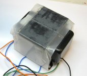
The Quicksilvers shipped today - delivery is scheduled for tomorrow, as the Quicksilver guy is just up in Stockton. The package weight is 21 lb, so I have some expectations as to quality. It'll be interesting to see how these compare to the 3k Transcendar "jumbo" transformers I have. I also have some fairly wimpy "would be James" transformers I got through E-pay from Taiwan. I should probably throw them into the comparison as well, as I haven't given them any bench testing. Lord knows what's actually inside them.
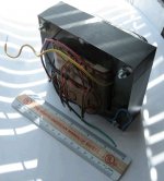
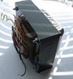
Measurements on the bench with a 50V, 300 Hz source indicate a turns ratio of 20:1 (3200 ohms: 8 ohms), and a primary inductance of 19H.
Hello Wrenchone and All,
Now that your new transformers are safe at their new home let me toss out a question.
I recall reading some Lundahl literature that said that Single End output transformers are gaped for an optimum idle current and any increase or decrease from the optimum idle current will degrade the output quality. Something like there is a center best level, most linier, level of flux. Higher current is closer to saturation. A lower level of flux looses linearity the other direction.
Your transformers are 120 ma what happens to the output quality if they are biased at say 90 or 150 ma?
Peter are you on line?
DT
All just for fun!
They are gapped for a maximum peak current, when all is said and done. If you run your bias too hot, you'll saturate early on the positive output peak. If you run your bias too low, you'll run out of excursion early on the negative output peak. Best operation would be biasing for symmetric clipping for a given set of conditions, which is a juggle between tube characteristics, B+, and transformer maximum current.
Last edited:
As far as I can tell. the current ratings on SE transformers refer to the max amount of DC bias level, with the expectation that one will hit 2X that level on max positive peaks, and run the current down to zero at the negative peaks, In any situation, this is the max that you can wring out of a given SE design. How liberally this is specified will depend on the transformer designer. Some will design their transformers to leave some room at the top end, and others will design so that the positive peak is at the ragged edge of saturation.
With an SE design, what goes up must come down, so that the negative swing can be no higher/lower than the DC bias level - that's it...
With an SE design, what goes up must come down, so that the negative swing can be no higher/lower than the DC bias level - that's it...
Hello Wrenchone,
Thank you for your discussion of Bias current in / for SET output transformers. Considering many valves have data sheets and plate curves as long as your arm. It is funny odd that output transformers do not. It seems that the characteristics including load line of the transformer and output tube should be laid on the light table looking for a good pairing.
Thinking those thoughts let me presume and suggest for your bread board a pairing of a NOS Mullard EL34 with your new output transformers. Perhaps not too much negative feedback would required to adjust the output impedance.
DT
All just for fun!
These transformers would not be well-served by something as small as an EL34 - besides, I don't have any. I'll be looking at the 6550s and "super" 6BG6GAs I have on hand, which are probably up to the job I have in mind. I may also lay in a supply of GU50s, as they are extremely cheap, and they have 40W plate dissipation capability. The low G2 voltage rating (250V) is troubling, but I may be able to get around that with a suitable resistor value for connecting G2 to anode.
At any rate, I have many other things in progress (I won't list them, but including sand and vacuum state, the number is probably >10) that I need to get out of the way before I can really devote my attention to this.
Today I'll take some pictures and measurements of my "Would Be James" transformers. If weight is any indication, these will be weak kid sisters compared to the Quicksilver monsters.
I was thinking while shaving this morning of some way I could do a measurement of the current capability for a given unknown SE transformer. A current-limited switch and a voltage source of sufficient rating, with a rugged clamp to protect switch and transformer may be the simplest solution.
If you simply switch the transformer primary into a voltage source, you'll get a current ramp dependent on input voltage and inductance - a rough check on the large signal inductance, and also a rough check for liniarity of the ramp. The saturation point indicates the absolute maximum current rating for the transformer. One would back off from this by a TBD factor for normal operation. One can also check a transformer at its rating, if known, to determine how close to the edge it really is, and whether the current/power rating is realistic.
Last edited:
I may also lay in a supply of GU50s, as they are extremely cheap, and they have 40W plate dissipation capability. The low G2 voltage rating (250V) is troubling, but I may be able to get around that with a suitable resistor value for connecting G2 to anode.
250V rating as you may see from specs is for linear pentode amplifiers. In triode mode they work well with 400V B+, 100 mA idle, no need for any resistors.
...also, if you connect all 3 grids together you may get a nice right-handed triode, but you have to drive it with grid currents. One pair of such "triodes" can give in PP about 200W of output power.
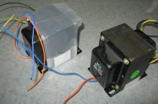
Here's a pic of one of a pair of "Would Be James" transformers, bought from an E-pay seller in Taiwan. It weighs in at 5.4 pounds (that includes the fancy case and potting), so I would suspect that it's capable of 10W or less, unless some cheating was done on primary inductance/current capability (likely). It looks nice, anyway. Measurements will follow.
Attachments
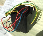
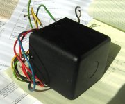
These transformers look to be from a lot of screw-ups. The calculated impedance for the 8 ohm tap is 2500 ohms, but 2800 ohms for the 4 ohm and 16 ohm taps. There's a very hot secondary tap as well whose purpose I don't immediately understand. For 50V input the 4, 8, and 16 ohm taps give me 1.89V, 2.83V, and 3.77V respectively, while the hot tap gives 18.7V - maybe this is for some sort of cathode feedback.The no-load excitation current was 0.43 mA for 50V, 300 Hz excitation. This calculates out as 62H primary inductance. This value is suspiciously high for such a small and low impedance transformer, which means that the primary resistance will be real high (lotsa turns), and/or the primary current capability will be pretty low.
The primary resistance is relatively low (70 ohms) so I doubt these will be good for much current. It's a good thing I checked... They may work with a relatively small tube like the 6B4G/6S4S. I was thinking of pairing them perhaps with the 6S41S, but I fear that's way too ambitious. These may definitely be a candidate for the test method I was mentioning in my last post for determining their real current capability.
The primary resistance is relatively low (70 ohms) so I doubt these will be good for much current. It's a good thing I checked... They may work with a relatively small tube like the 6B4G/6S4S. I was thinking of pairing them perhaps with the 6S41S, but I fear that's way too ambitious. These may definitely be a candidate for the test method I was mentioning in my last post for determining their real current capability.
Hello Wrenchone and All,These transformers would not be well-served by something as small as an EL34 - besides, I don't have any. I'll be looking at the 6550s and "super" 6BG6GAs I have on hand, which are probably up to the job I have in mind. I may also lay in a supply of GU50s, as they are extremely cheap, and they have 40W plate dissipation capability. The low G2 voltage rating (250V) is troubling, but I may be able to get around that with a suitable resistor value for connecting G2 to anode.
I was thinking while shaving this morning of some way I could do a measurement of the current capability for a given unknown SE transformer. A current-limited switch and a voltage source of sufficient rating, with a rugged clamp to protect switch and transformer may be the simplest solution.
Those are creative thoughts. A test bench procedure to identify the characteristics of the latest output transformer find on e-bay. The goal being the best match of valve to transformer. What parameters to match? Let me put a couple of suggestions on the list.
1) Valve rp vs transformer impedance.
2) Valve bias current times bias voltage (dissipation watts) vs transformer optimum bias current.
3) (add items)
More thoughts about transformer test procedures and equipment.
1) Adjustable bias DC current
2) AC frequency sweep
3) Adjust AC voltage
4) Run FFT at output
5) Run frequency analysis
6) Record test data; saturation, power in watts, frequency response, distortion and the adjusted DC bias and AC input voltage.
7) Zo test (procedure needed)
DT
All just for fun!
More thoughts about transformer test procedures and equipment.
1) Adjustable bias DC current
2) AC frequency sweep
3) Adjust AC voltage
4) Run FFT at output
5) Run frequency analysis
6) Record test data; saturation, power in watts, frequency response, distortion and the adjusted DC bias and AC input voltage.
7) Zo test (procedure needed)
I did some testing along these lines several years ago. Some of the results are here:
Budget OPT's
The short story is that there is an optimum bias current for a given SE OPT. Unfortunately it moves around a bit with power and test frequency. On some amps you can see a sharp null in the 3rd harmonic as the bias current is varied.
Wrenchone, did you ever run any tests on the big Fender P-P transformers you got from Ebay? I might get a pair if the HF response was acceptable. The big red board is on hold for lack of big OPT's in the 3K ohm range.
I haven't run any HF tests on the big Fenders - be aware that there are now even bigger Fenders available on E-pay, though more expensive.
The primary inductance was quite satisfactory on the one I tested (660H), so I suspect the low end will be ok. I wasn't all that worried about the high end, as I finally have a biamped system in place. I was also thinking of using a supplementary HF transformer (as suggested by KYW in a private email) if the HF response was deficient. If the low end limit on the HF transformer was set at 5kHz or so, I could even use a ferrite core HF transformer. Keep in mind I'm always working the wild side of the street...
The thing that set me back a little was that the transformers are really 8k into an 8 ohm load, which means I'd have to use a high B+ to get a lot of power. This is not really an issue with a screen-driven sweep tube amp, though.
The screening process I've suggested so far would be more or less a triage sort of deal to sort out transformers as suitable for a given power level/tube group.Those who want to do more extensive tests are invited to do so with their own resources and report back.
The reports from the last meeting of the Triode Group/Conspiracy/Conglomeration/Meeting in France are suggested as a starting point, as a test circuit was posted, along with test results for a fair number of transformers, many of which cost a lot more money than I'm willing to shell out at this point. What I found interesting is that some of the more subjectively appealing transformers had less than appealing square wave response. There is also a compendium of data available on various old stock transformers from folks like HK, Scott, Fisher, etc. (try the Triode Electronics site or Pete Millett's pages to find it) that is interesting.
Next up, a Transcendar TT-010-OT. This transformer is one of the "baby budget" Transcendar series. Through the protective plastic film, you can see that the core stack is respectable. It weighs in at 4.1 lb, and looks like it might possibly be able to fit in the case for the "Would be James". With 50V, 300 Hz excitation at the primary, output voltage is 2.7V. This translates to an 18.5:1 turns ratio, or a 2.74k:8 ohm impedance ratio. This is fairly close to the stated 3k impedance value. Open secondary excitation current is 0.97 ma at 50V, 300 Hz excitation. This works out to a primary induxctance of 27H, which is reasonably respectable for a transformer of that size and impedance. I'll take a look at the 15W Transcendar when I find it in my pile, and may also drag in a One Electron for comparison.
Attachments
A two-for one deal here. The photo shows a One electron UBT-3 and one of the large "original series" Transcendar 3k, 15W output transformers. Both have 4 ohm and o ohm output taps, but no primary ultralinear taps.
Transcendar:
Tested with 50V, 300Hx excitation, findings were as folows - 4ohm (Blk-yel) yields 1.925V output. Turns ratio calculated as 25.97:1, impedance ratio, 2699 ohms: 4 ohms. The 8 ohm tap (Blk-Grn) yeilded 2.716V output. Calculated turns ratio is 18.4:1, impedance ratio 2711 ohms : 8 ohms. This is the first tapped secondary SE transformer I've measured where there has been reasonable impedance agreement between the two secondary taps. Open circuit excitation current was 0.78 ma, for a calculated primary inductance of 34H. Primary resistance is 263 ohms.
One Electron UBT-3 :
Teated with 50V, 300 Hz excitation, output on 4 ohm tap (Blk-Yel) is 1.97V, so calculated turns ratio is 25.38 : 1, and an impedance ratio of 2577 ohms : 4 ohms. The 8 ohm tap (Blk-Grn) output was 2.852V, for a calculated turns ratio of 19.36 :1, and a calculated impedance ratio of 2998 ohms : 8 ohms. As can be seen there is a large variance in reflected impedance between the two secondary taps. Open circuit excitation current was 0.89 ma, for a calculated primary inductance of 29.8 H. Primary resistance is 294 ohms.
George has noted the high primary resistance of the One Electron UBT-3 in the past, and its implications for efiiciency and output power. The Transcendar looks to be similarly lossy. I should go back and measure the resistance on the Quicksilver transformer as a comparison. Having said that, this is an indication that there are enough turns to support the claims for output power, maximum bias current, and primary inductance. The indictance reading on the "Would Be James" is suspiciously high as compared to its low primary resistance, an indication that it would no support as much bias current/power as the other transformers measured in this thread.
Attachments
I'm wondering whether the WBJ is using a core with a higher permeability than the others? I've run across a few permalloy core transformers that are exceptionally good and very small relative to their power handling capability. Perhaps you lucked out or these are questionable as you say. The low excitation currents seem to imply that the core material might be better than average.
Those WBJ cans and potting could weigh significantly less than 1 lb..
Hoping you got a good deal.
Those WBJ cans and potting could weigh significantly less than 1 lb..
Hoping you got a good deal.
- Home
- Amplifiers
- Tubes / Valves
- Uses for Quicksilver Transformers