Hello all,
I was wondering if I could get a quick sanity check to ensure that I have a reasonable basic design process for a tube RIAA phono preamp. What follows is the process I've been using; I am fairly certain it is more or less correct, but it would be nice to have confirmation of that.
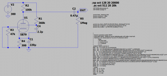
Stage 1: Design the actual gain stage(s) using normal methods, looking at distortion, reasonable frequency response, overload conditions, etc, and tweaking until you're satisfied with the result. For this example I put a single gain stage (probably a rather crummy one at that) together just to play with, followed by the coupling cap and grid leak to the next tube that would be in a real phono preamp.
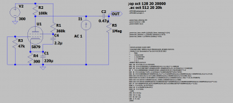
Stage 2A: Determine the nominal output impedance from the gain stage being examined by placing a current source from ground to the node of interest, setting the AC current of that current source to amplitude 1, and then running an AC sweep.
Stage 2B: Plotting the magnitude of the voltage on the node in question, dividing that plot by a factor of I(I1) or whatever the current supplied by the current source is, and reading the result off the plot, now in ohms (or kohms, etc).
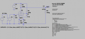
Stage 3A: Use a voltage controlled voltage source as the input to the gain stage in question. Set the Laplace transform of the VCVS to the inverse of the equalization curve you're trying to correct for (Columbia Lp, RIAA, London FFRR, whatever). In this case I'm using RIAA.
Stage 3B: Run a frequency sweep to ensure that the inverse equalization looks correct.
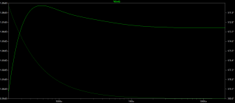
Stage 4A: Calculate the correct values of capacitance and resistance for the passive equalization network using the known formulas. Say, for instance, using the kabusa.com calculator, set R1 to be the impedance found in Stage 2A, in this case ~71 kilohms. Insert the equalization network, and set the resistance and capacitance values to those calculated.
Stage 4B: Run the sweep again, and check to see how much error the calculated network has. In this case, it doesn't look great, but doesn't look too terrible either.
Finally, take the calculated values of the caps and resistors for the equalization network and play around with them, trying to find tolerable values that are commercially available, or series and parallel combinations of available components, while trying not to completely destroy the conformance to the equalization curve in question.
Attached are PNGs showing the process I've used. Is this method fundamentally correct, or am I making huge mistakes I'm not aware of?
I was wondering if I could get a quick sanity check to ensure that I have a reasonable basic design process for a tube RIAA phono preamp. What follows is the process I've been using; I am fairly certain it is more or less correct, but it would be nice to have confirmation of that.
Stage 1: Design the actual gain stage(s) using normal methods, looking at distortion, reasonable frequency response, overload conditions, etc, and tweaking until you're satisfied with the result. For this example I put a single gain stage (probably a rather crummy one at that) together just to play with, followed by the coupling cap and grid leak to the next tube that would be in a real phono preamp.
Stage 2A: Determine the nominal output impedance from the gain stage being examined by placing a current source from ground to the node of interest, setting the AC current of that current source to amplitude 1, and then running an AC sweep.
Stage 2B: Plotting the magnitude of the voltage on the node in question, dividing that plot by a factor of I(I1) or whatever the current supplied by the current source is, and reading the result off the plot, now in ohms (or kohms, etc).
Stage 3A: Use a voltage controlled voltage source as the input to the gain stage in question. Set the Laplace transform of the VCVS to the inverse of the equalization curve you're trying to correct for (Columbia Lp, RIAA, London FFRR, whatever). In this case I'm using RIAA.
Stage 3B: Run a frequency sweep to ensure that the inverse equalization looks correct.
Stage 4A: Calculate the correct values of capacitance and resistance for the passive equalization network using the known formulas. Say, for instance, using the kabusa.com calculator, set R1 to be the impedance found in Stage 2A, in this case ~71 kilohms. Insert the equalization network, and set the resistance and capacitance values to those calculated.
Stage 4B: Run the sweep again, and check to see how much error the calculated network has. In this case, it doesn't look great, but doesn't look too terrible either.
Finally, take the calculated values of the caps and resistors for the equalization network and play around with them, trying to find tolerable values that are commercially available, or series and parallel combinations of available components, while trying not to completely destroy the conformance to the equalization curve in question.
Attached are PNGs showing the process I've used. Is this method fundamentally correct, or am I making huge mistakes I'm not aware of?
Attachments


What follows is the process I've been using
The second tube stage will also have some Miller effect input capacitance.
This should be included in the model, in parallel with C5 or R5.
Last edited:
I hadn't considered that yet as I was just playing with the single gain stage for the moment to make sure I could actually get a reasonably flat response back out of the equalization network, but you're correct of course, and I'll start considering that as I continue to play around with it.
I have to say, the more I learn about LTSpice's various functionalities, the more I love it. Digital bread-boarding is about a hundredth of the effort of actually wiring up a temporary circuit.
I have to say, the more I learn about LTSpice's various functionalities, the more I love it. Digital bread-boarding is about a hundredth of the effort of actually wiring up a temporary circuit.
Attached are PNGs showing the process I've used. Is this method fundamentally correct, or am I making huge mistakes I'm not aware of?
As SY pointed out in "His Master's Noise", one shouldn't be reliant on the output impedance of the first stage in and of itself -- it will vary depending upon the tube and will change over time.
That's why he utilized the D3a with high mu, low rp, and low noise. There are other pentodes, triode connected, which fit the bill as well.
- Status
- Not open for further replies.