I am using the MC33171N as a differential op amp. (I’ve attached the schematic of that section.)
The general design is based in part on the IC’s product sheet (which I’ve attached) as well as similar designs on the net. One, in particular, includes a 4.7uF electrolytic cap in series with each input.
Would someone tell me what purpose those caps serve?
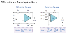
Also, from examples on the net I saw that the feedback resistor was equal to the resistor put to ground on the non-inverting side. Is this actually correct? My understanding is that for a gain (factor) of 10 I would use a feedback resistor ten times the value of the non-inverting side grounded resistor. (What is that resistor called, and what does it do?)
The general design is based in part on the IC’s product sheet (which I’ve attached) as well as similar designs on the net. One, in particular, includes a 4.7uF electrolytic cap in series with each input.
Would someone tell me what purpose those caps serve?
Also, from examples on the net I saw that the feedback resistor was equal to the resistor put to ground on the non-inverting side. Is this actually correct? My understanding is that for a gain (factor) of 10 I would use a feedback resistor ten times the value of the non-inverting side grounded resistor. (What is that resistor called, and what does it do?)
Attachments

For a bipolar op amp, the inputs should see equal DC resistances to minimize DC offset and drift.
Except for audio or ac signal where offset and drift are irrelevant - its even got a fat electrolytic on the output in this case...For a bipolar op amp, the inputs should see equal DC resistances to minimize DC offset and drift.
The main issue with the circuit is its not a differential amplifier since R12 and R13 are very different values, meaning the common mode gain is not zero.
High value feedback resistors can make stability more depedent on layout since stray capacitances will dominate the circuit up at MHz frequencies.
thank you for your reply . . . i will adjustFor a bipolar op amp, the inputs should see equal DC resistances to minimize DC offset and drift.
thank you for your reply - understoodExcept for audio or ac signal where offset and drift are irrelevant - its even got a fat electrolytic on the output in this case...
The main issue with the circuit is its not a differential amplifier since R12 and R13 are very different values, meaning the common mode gain is not zero.
High value feedback resistors can make stability more depedent on layout since stray capacitances will dominate the circuit up at MHz frequencies.
- Home
- Design & Build
- Electronic Design
- Use of Capacitors and Resistor Values in Differential Op Amp