Actually, the mu output of a depletion mode CCS is commonly used when lower output impedance is desired:
Active loads and signal current control
I use it in my 26 preamp; the output impedance is much lower than the 8000R typical of the 26, which lets me drive a Bent Audio autoformer volume control in parafeed as my output "transformer", with flat response below 10Hz (the limit of my RTA software).
Hi,
Out of curiosity, which 'type' of CCS are you using, what is the value of parafeed capacitor and which model of AVC/TVC are you using?
FWIW, my set up is similar but there is a slight LF rise (not what I'd call a peak) at about 10-15 Hz.
Sun.
Hi,
Out of curiosity, which 'type' of CCS are you using, what is the value of parafeed capacitor and which model of AVC/TVC are you using?
FWIW, my set up is similar but there is a slight LF rise (not what I'd call a peak) at about 10-15 Hz.
Sun.
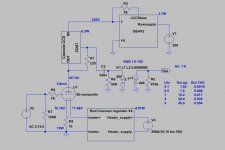
CCS is the K&K Audio compact cascode CCS - small, simple, cheap and effective.
Parafeed is a "lossy parafeed" setup, with a 1uF Duelund Cast, and 3.3uF Mundorf Supreme and a 8080R resistor. The resistor and Mundorf cap are in parallel with the Duelund; this flattens out the response and extends it down to ~4Hz corner frequency, according to my calculations. On my RTA it's flat to 10Hz (the limit of the RTA).
AVC is Bent Audio silver-wound autoformer, with core stacked 3x3 for ~150H inductance.
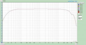
Picture one shows the frequency response of my preamp from -6dB to -24dB on the AVC, the normal range I use it in. Nice and flat.
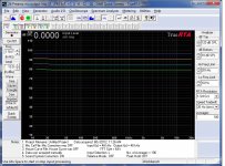
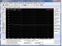
The second picture shows the effect of the lossy parafeed (3.3uF + 8080R) on the FR. The curve with the hump between 10Hz and 20Hz is only the 1uF Duelund cap, the other graph has the 3.3uF+8080R in parallel with the 1uF; you can see how that flattens the hump right out.
The second picture shows the effect of the lossy parafeed (3.3uF + 8080R) on the FR. The curve with the hump between 10Hz and 20Hz is only the 1uF Duelund cap, the other graph has the 3.3uF+8080R in parallel with the 1uF; you can see how that flattens the hump right out.
Attachments
Picture one shows the frequency response of my preamp from -6dB to -24dB on the AVC, the normal range I use it in. Nice and flat.
The second picture shows the effect of the lossy parafeed (3.3uF + 8080R) on the FR. The curve with the hump between 10Hz and 20Hz is only the 1uF Duelund cap, the other graph has the 3.3uF+8080R in parallel with the 1uF; you can see how that flattens the hump right out.
I like what Voltsecond did with the lossy parafeed calculator which was available some time ago and I'd used the same with a CCS fed shunt cap (yeah I know) to driver plate and playing around with values closely resembled the measurements. You know, all that and I'd forgotten all about it, will revisit with the mu out to AVC, many thanks for the info.
In my #26 preamp I use cascode DN2540 CCS, 100nF V-Cap // 220nF FT-3 teflon parafeed capacitors and S&B Tx-102 TVC.
I also have the S&B TX-102.
You're fortunate to have the high load to the secondary like that !
Mine drives another transformer (amplifier input) which introduces some obstacles 🙂
- Status
- Not open for further replies.