I have a new question...
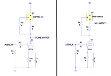
I was reading about the mu-follower (vacuum tube used as active plate load for a vacuum tube), and noticed that whenever you see that kind of stage, the output is almost always taken from the cathode of the upper tube. I gather this is called the "mu output."
However, I've noticed that whenever you see a triode with a 10M45S or DN2540 MOSFET as an active plate load, the output from that stage is almost always taken from the plate of the tube (on bottom), instead of from the source of the MOSFET.
Why is that? Is there something wrong with taking the output from the source of the load MOSFET?
Assuming that the stage is lightly loaded, do the two outputs sound noticeably different? I can't see any reason why you'd use the plate output from the tube instead of the source output from the MOSFET. But you know, I'm probably missing something...
--
Attachments
A cascode is better due to excessive gate to drain capacitance in a single device implementation which loads the plate of the tube at higher frequencies whether used as a simple CCS or mu-follower. I use a single mosfet mu-follower based on DN2540 in one of my phono stages, works much better than the tube driving the capacitance of a long interconnect, but the rp of the tube in question is about 5K. (Next time I will use a cascode ccs)
Taking the output from the FET source will increase the ability to drive lower impedance loads. Taking it from the plate will be only giving the tube an active (current source) load so the input impedance of the next stage will usually reduce gain.
Actually, the mu output of a depletion mode CCS is commonly used when lower output impedance is desired:
Active loads and signal current control
I use it in my 26 preamp; the output impedance is much lower than the 8000R typical of the 26, which lets me drive a Bent Audio autoformer volume control in parafeed as my output "transformer", with flat response below 10Hz (the limit of my RTA software).
Active loads and signal current control
I use it in my 26 preamp; the output impedance is much lower than the 8000R typical of the 26, which lets me drive a Bent Audio autoformer volume control in parafeed as my output "transformer", with flat response below 10Hz (the limit of my RTA software).
Thanks for the reply. Yes, I know a cascode pair of MOSFETs is better for a plate load, much higher impedance load for the triode, gate capacitance doesn't affect it as much, etc. All good points. So...
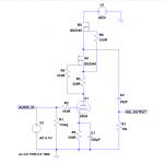
Is it not possible to use the "mu follower output" from a cascode-pair MOSFET plate load? I tried modeling it in LTSpice, and it looks like it should work. I loaded it heavily (10k ohms) and found that the circuit has half the gain from its plate into the 10k load as compared to with the output taken from the source of M2 (the top DN2540 in the cascode pair), as shown in the attached schematic.
If this works, then why haven't I seen this? Maybe I missed it somewhere...
Thanks
Attachments
Last edited:
Why, there it is:
However, that shows the mu follower output taken from the source of the bottom MOSFET in the cascode pair. Is that the better place from which to take the output?
thanks for the replies...
______________________________________________________
Gary Pimm writes:
Hmmm.... Does that mean the lower MOSFET has the more stable operating conditions, so its source is the better place from which to take the output signal?
--
An externally hosted image should be here but it was not working when we last tested it.
However, that shows the mu follower output taken from the source of the bottom MOSFET in the cascode pair. Is that the better place from which to take the output?
thanks for the replies...
______________________________________________________
Gary Pimm writes:
Performance in a cascode circuit improves because the upper mosfet isolates the lower mosfet from voltage variations. At higher frequencies where the capacitance issues come into play the AC leakage current that couples across the drain to the gate of the upper mosfet is routed back into the current summing node of the CCS, the source of the lower mosfet. There will be very little AC leakage current from the drain to gate of the lower mosfet, as it is isolated from the AC signal by the upper mosfet. With the upper mosfet handling the AC signal voltage the lower mosfet basically operates at DC.
Hmmm.... Does that mean the lower MOSFET has the more stable operating conditions, so its source is the better place from which to take the output signal?
--
Last edited:
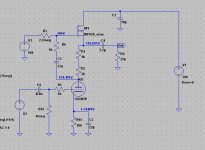
You might be interested in this.
Whoa. I think that one sailed right over my head. Yes, very interesting...
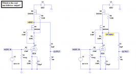
The right side circuit is the usual "cascaded" Mu follower. The top Mosfet is really just used as a bootstrap for the bottom Mosfet's drain, to lower gate input capacitance. (ie, the V Cgd is tracking) So the signal is going through the bottom Mosfet as a Hi Zin / Lo Zout buffer/follower. (avoiding any loading on the tube plate)
Using the left circuit would be putting the signal through two sequential Mosfet followers. Un-necessarily adding more Mosfet Vgs gain effects.
Putting the load on the tube plate, loads the tube down with the load Z, so will give less output V and more distortion.
Using the left circuit would be putting the signal through two sequential Mosfet followers. Un-necessarily adding more Mosfet Vgs gain effects.
Putting the load on the tube plate, loads the tube down with the load Z, so will give less output V and more distortion.
Last edited:
A cascode is better due to excessive gate to drain capacitance in a single device implementation which loads the plate of the tube at higher frequencies whether used as a simple CCS or mu-follower. I use a single mosfet mu-follower based on DN2540 in one of my phono stages, works much better than the tube driving the capacitance of a long interconnect, but the rp of the tube in question is about 5K. (Next time I will use a cascode ccs)
I think the capacitance issue of a single Mosfet load can be overstated. I use a IXY chip as a parafeed plate load and can hear no significant roll off.
Shoog
OK, here's the question now. Which is the 'real' mu-follower output? (see attached)
The right one is what I use with excellent results. An interesting fact is that this is the only way the loaded tube will actually stay in constant current mode during operation, otherwise, the current drawn from the plate will cause it to vary from CC operation.
I think the capacitance issue of a single Mosfet load can be overstated. I use a IXY chip as a parafeed plate load and can hear no significant roll off.
Shoog
This depends very heavily on the rp of the tube, low rp tubes will perform quite well with a single mosfet follower, higher rp tubes will perform measurably and audibly better with the cascode. I'm currently using tubes with an rp <= 5K with single mosfet mu follower and it works well, and makes somewhat greater than 30kHz bandwidth.
Good analysis.This depends very heavily on the rp of the tube, low rp tubes will perform quite well with a single mosfet follower, higher rp tubes will perform measurably and audibly better with the cascode. I'm currently using tubes with an rp <= 5K with single mosfet mu follower and it works well, and makes somewhat greater than 20kHz bandwidth.
People should consider what tube they intend to use before going the extra mile for the cascode.
My design was using a E55L in triode mode (rp = 600R) which will have low rp and will be able to drive the gate capacitance well. Something like a 27 valve would probably benefit from the cascode (rp = 9000R).
I think the issue is that many times people don't understand why they are doing it and go to a lot more trouble for no real benefit.
Shoog
I don't get this; I use only single FET gyrator type plate loads (on all stages including output). In both SE and PP I measure -3dB somewhere in the 50kHz to 100kHz region.
I got 120 kHz out of a tube with rp = 40k with a cascode CCS. Performance probably wouldn't have been that great without the cascode in this instance.
I would probably always use a cascode CCS, but that's because I had 100 cascode CCS PCBs made so it would actually be harder for me to make a non-cascode CCS.
But it certainly isn't required in every instance.
I would probably always use a cascode CCS, but that's because I had 100 cascode CCS PCBs made so it would actually be harder for me to make a non-cascode CCS.
But it certainly isn't required in every instance.
I sim'd the two different cascode CCS arrangements, into loads as low as 1k. The arrangement on the left seems to have lower output Z, since output voltage is higher into the 1k load than from the arrangement on the right. But I can see that there are good reasons for preferring the arrangement on the right, and that's the consensus. I'll go with that, since you guys are the pros!
It makes sense that a tube with low rp would drive the gate C of the MOSFET better. Thanks for pointing that out.
If using a 6DJ8/ECC88 at 6mA or higher plate dissipation (rp of about 4k), do you think the cascode CCS would be necessary, or would bandwidth be OK with the single MOSFET CCS? What about 12AT7 (rp of about 15k)?
The problems come when using something like 12AX7 or 6SL7. I've seen various suggestions for that situation...
For me, the attraction of using depletion mode MOSFETs is that you don't need the additional supply for the gate of the CCS semiconductor. Makes it easier for the hobbyist.
--
Actually, the mu output of a depletion mode CCS is commonly used when lower output impedance is desired:
Active loads and signal current control
I use it in my 26 preamp; the output impedance is much lower than the 8000R typical of the 26, which lets me drive a Bent Audio autoformer volume control in parafeed as my output "transformer", with flat response below 10Hz (the limit of my RTA software).
Hi,
Out of curiosity, which 'type' of CCS are you using, what is the value of parafeed capacitor and which model of AVC/TVC are you using?
FWIW, my set up is similar but there is a slight LF rise (not what I'd call a peak) at about 10-15 Hz.
Sun.
- Status
- Not open for further replies.
- Home
- Amplifiers
- Tubes / Valves
- Use "mu output" from depletion mode MOSFET load?