Does anyone know where I can get a schematic for a USB to SPDIF converter, like the ones from empirical audio. Thanks!!! I like their concept but $500 is a bit steep. Preferably somethng that can plug into a Mac without needing drivers.
The chip is the PCM2902 or PCM2906, works in win, Mac and linux without drivers, the schematic is on the datasheet.
You find also some schematics here in the Digital section of the forum.
Bye,
Paolo
You find also some schematics here in the Digital section of the forum.
Bye,
Paolo
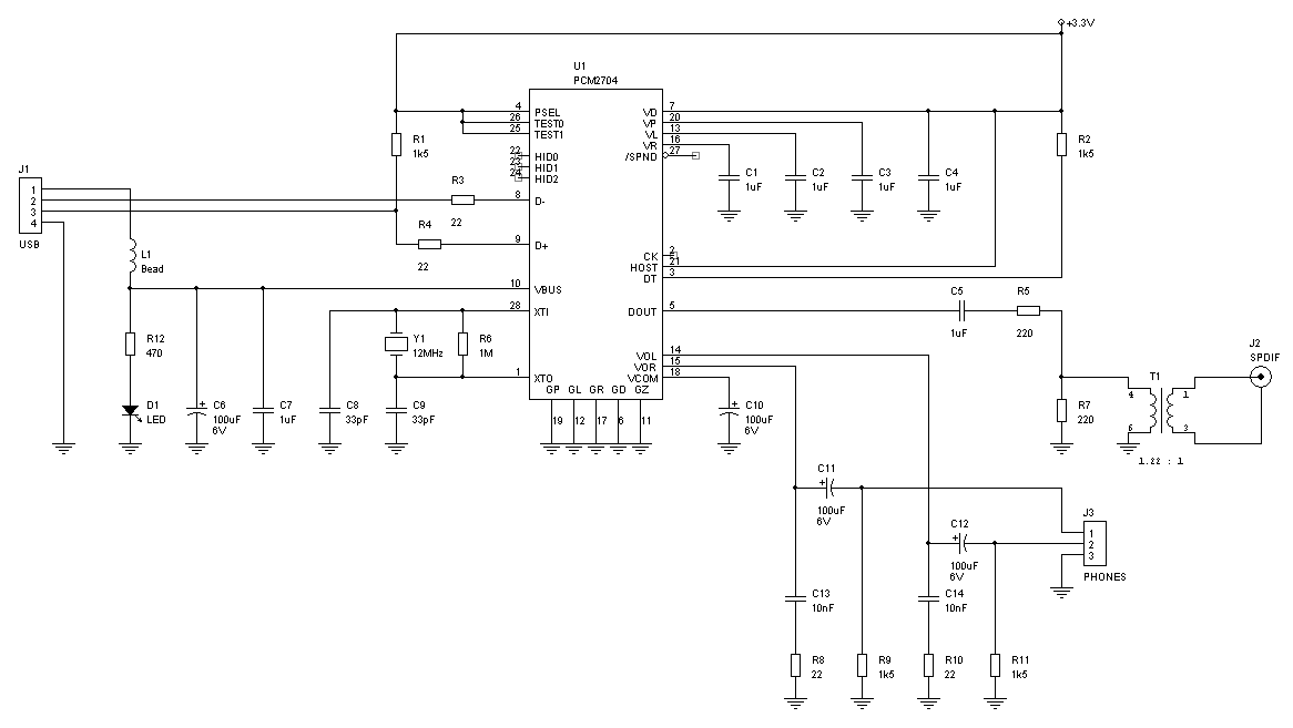
I used the PCM2704. Very straightforward. Made a PCB (called the HAGUSB), which I was planning on selling. But instead just put the circuit onto the motherboard of my new DAC. Anyway, here's the schematic. I left off the headphone amplifier output stuff. Just straight USB to clean S/PDIF. Output is 75 ohm with 1.2:1 tranny.

Circuit is self-powered by USB cable, isolated from CD player via tranny. Windows XP (and I suppose Mac) recognized it as soon as I plugged it in. After 30 seconds or so of automatic configuration, my laptop was playing CDs through the USB port to my external DAC. No software. No drivers. No mess. Them folks at TI did a great job with this part.
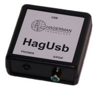
Here's my test board.

jh🙂

Circuit is self-powered by USB cable, isolated from CD player via tranny. Windows XP (and I suppose Mac) recognized it as soon as I plugged it in. After 30 seconds or so of automatic configuration, my laptop was playing CDs through the USB port to my external DAC. No software. No drivers. No mess. Them folks at TI did a great job with this part.
Here's my test board.

jh🙂
One thing I have been wondering about these USB to SPDIF parts: what clock controls the audio data rate? In other words, does the PCM2704 pull the data from the PC so that the 12 MHz crystal in your schematic determines the data rate (and hence the jitter on the SPDIF) or does the PC push the data into the PCM2704, in which case the data rate is set by a clock in the PC (thus causing SPDIF jitter by passing jitter from the PC clock)? Or is there some sort of ASRC involved?
It is very much ASRC. The USB side is sent in data packets every couple of milliseconds. Then sits idle until next packet. Not sure if it is push or pull. The USB data rate is fixed, the packet rate is variable. There is networking stuff going on, like other items on bus, acknowledges, re-sends for error correction, etc. The TI chip buffers the data and then re-clock it out at a constant rate.
Only way they can get the right output frequency is via some synthesizer onboard. I haven't dug into it deep enough to figure out exactly how they do it, or how sensitive it is to jitter or the xtal charateristics. Nothing depends on the clock in PC, except to make sure the USB data rate is close enough so that it can be received without too many errors.
So asynchronous pulsed data in, constant data out.
jh🙂
From the PCM2702 datasheet:
The newly developed SpAct™ (Sampling Period Adaptive Controlled Tracking) system recovers a stable, low-jitter clock for internal PLL and DAC operation from the USB interface audio data
The same applies for PCM290x family (that has also the spdif input).
The newly developed SpAct™ (Sampling Period Adaptive Controlled Tracking) system recovers a stable, low-jitter clock for internal PLL and DAC operation from the USB interface audio data
The same applies for PCM290x family (that has also the spdif input).
So how about sample rate?
How does Windows drive it? 32, 44 or 48 khz depending on source, or directsound based sample rate conversion?
Is the Windows volume control working? If it does, possibly the sound is not 100% pure the source signal. (Some even say you never get more than 14bit if the Windows mixer is in play)
and how about higher Fs and bitrate? 96/24?
Thanks
mp006ltk said:Does anyone know where I can get a schematic for a USB to SPDIF converter, like the ones from empirical audio. Thanks!!! I like their concept but $500 is a bit steep. Preferably somethng that can plug into a Mac without needing drivers.
Edirol has just announced a new USB dongle, UA1-EX that supports 24/96 IO. I use the older UA5 product, the new drivers install and work well. Seems it will be $79.95 street price. Nice thing too it's both input and output. They also claim native Mac/PC USB driver support.
EDIT- I just noticed a catch, the SPIDIF is optical only so you might need a converter (I've seen them for $20 or so).
How does Windows drive it? 32, 44 or 48 khz
It does all of them. Sample rate data is included in the header of the audio packet information. The chip might even do 96k, I forget.
USB Data is data, no clock is sent. Only a few bits indicating what the clock rate should be. Output S/PDIF embeds a newly generated clock with the data.
I think the normal "sounds" of Windows is at 48k. That is, the chimes, clicks, bells, and other mouse & keyboard sounds. Only an audio CD is played back at the 44.1k rate.
jh🙂
hagtech said:
It does all of them. Sample rate data is included in the header of the audio packet information. The chip might even do 96k, I forget.
USB Data is data, no clock is sent. Only a few bits indicating what the clock rate should be. Output S/PDIF embeds a newly generated clock with the data.
I think the normal "sounds" of Windows is at 48k. That is, the chimes, clicks, bells, and other mouse & keyboard sounds. Only an audio CD is played back at the 44.1k rate.
jh🙂
Works also at 96 kHz (under XP) but unfortunately the bandwidth is limited to 24 kHz (as from datasheet.. max sample rate 48 kHz).
An externally hosted image should be here but it was not working when we last tested it.
(click to enlarge)
There's no ASRC in the PCM270x parts.
A clever adaptation of PLL and DLL with an adaptive corner frequency, aka SpAct, recovers a sample clock by using the delay between adjacent USB packets and the long term frequency. Google for "spact pll" and you'll eventually find a multi-page article on an industry website which explains how SpAct was developed.
A clever adaptation of PLL and DLL with an adaptive corner frequency, aka SpAct, recovers a sample clock by using the delay between adjacent USB packets and the long term frequency. Google for "spact pll" and you'll eventually find a multi-page article on an industry website which explains how SpAct was developed.
There's no ASRC in the PCM270x parts
I don't agree with this. But then, maybe we're saying the same thing but arguing over word definitions.
The USB data is not "clocked". It does not come in at 44.1k, or 96k, or any other sample rate. It comes in data packets about every 1ms (at 48MHz, I think). Therefore, the output S/PDIF clock is independent of the incoming USB data packet rate.
The spact works only on the 12MHz xtal tied to the PCM270x chip. The output clock (embedded in S/PDIF) is derived from the local 12MHz. There is clocking independence between input and output. Hence the need to buffer up to 1ms of audio data before it is output. To me, that is asynchronous.
jh🙂
hagtech said:I don't agree with this. But then, maybe we're saying the same thing but arguing over word definitions.
The USB data is not "clocked". It does not come in at 44.1k, or 96k, or any other sample rate. It comes in data packets about every 1ms (at 48MHz, I think). Therefore, the output S/PDIF clock is independent of the incoming USB data packet rate.
The spact works only on the 12MHz xtal tied to the PCM270x chip. The output clock (embedded in S/PDIF) is derived from the local 12MHz. There is clocking independence between input and output. Hence the need to buffer up to 1ms of audio data before it is output. To me, that is asynchronous.
jh🙂
The USB data isn't strictly clocked as SPDIF is... but the net data rate for a CD will still be 44.1. After 1000 seconds, your Windows machine will have sent 44100000 samples to the PCM290x.
The audio is delivered in isochronous packets of 128/256/512 bytes, coming in at a packet rate of 44100/256 Hz or whatever. This packet rate is used as the reference for the SpAct PLL.
ASRC implies asynchronous rate conversion of the data between the computer and the PCM part... in other words, the PCM part is spitting different audio samples at a different sample rate out its SPDIF port than the computer is actually feeding it.
I know for a fact this isn't true - I can play a DTS-encoded FLAC file on my computer and my HT receiver will detect DTS and decode it. Any ASRC process would prevent this from happening.
I used the PCM2704. Very straightforward. Made a PCB (called the HAGUSB), which I was planning on selling. But instead just put the circuit onto the motherboard of my new DAC. Anyway, here's the schematic. I left off the headphone amplifier output stuff. Just straight USB to clean S/PDIF. Output is 75 ohm with 1.2:1 tranny.

Circuit is self-powered by USB cable, isolated from CD player via tranny. Windows XP (and I suppose Mac) recognized it as soon as I plugged it in. After 30 seconds or so of automatic configuration, my laptop was playing CDs through the USB port to my external DAC. No software. No drivers. No mess. Them folks at TI did a great job with this part.
Here's my test board.
I want to know where the source +3.3V come from? Is it necessary to design the separated power supply?
Thanks

jh🙂
- Status
- Not open for further replies.
- Home
- Source & Line
- Digital Source
- USB to SPDIF Converter