Hi there,
I recently found the 3e audio DSP board and its very suitable for my needs, but I wanna go a step further to use the I2S input rather than the RCA in. I am a bit new to these things so I spoke to 3e audio, they said their DSP board only takes slave input. I am confused, I searched for USB to I2S board products (like on Aliexpress), there are tons but I dont really see them mentioning Master/Slave mode about their board. I dont know what product I could use, could anybody give me some help and point me to a USB to I2S product that could work with the 3e audio DSP board? Thanks a lot!
I recently found the 3e audio DSP board and its very suitable for my needs, but I wanna go a step further to use the I2S input rather than the RCA in. I am a bit new to these things so I spoke to 3e audio, they said their DSP board only takes slave input. I am confused, I searched for USB to I2S board products (like on Aliexpress), there are tons but I dont really see them mentioning Master/Slave mode about their board. I dont know what product I could use, could anybody give me some help and point me to a USB to I2S product that could work with the 3e audio DSP board? Thanks a lot!
Any of them will work.
Slave means that the DSP board expects all 3 lines to be an input. Master mode would mean the DSP board provides 2 of the 3 lines as output and expects the other board to provide the data line, which is usually an optional configuration most generic USB to i2s boards do not support.
Slave means that the DSP board expects all 3 lines to be an input. Master mode would mean the DSP board provides 2 of the 3 lines as output and expects the other board to provide the data line, which is usually an optional configuration most generic USB to i2s boards do not support.
I see! Thank you very much 🙂
And if you dont mind helping me a little further, I have another question:
So I see on the 3e audio DSP board there are pins:
LRCLK_IN
BCLK_IN
DATA_IN
and on a typical USB to I2S board I see:
MCLK
LRCK
SCLK
DATA
Then I assume, I should connect:
LRCK -> LRCLK_IN
SCLK -> BCLK_IN
DATA -> DATA_IN
right?
Have a good day.
Sorry to hijack thread but does the 3e DSP come will all cables or do you have to arrange separately?
You need to buy separate cable. It's not on their website, but you can find it on Aliexpress.
If you have any luck getting the DSP to work ,let me know.
In fact if anyone can help with the 3e Audio DSP - when I click 'Link Compile Download' I get an error report saying hardware not connected and thus am unable to save any changes to the EPROM board.
If you have any luck getting the DSP to work ,let me know.
In fact if anyone can help with the 3e Audio DSP - when I click 'Link Compile Download' I get an error report saying hardware not connected and thus am unable to save any changes to the EPROM board.
Mine has just arrived but I am finishing some other projects so it will be a while before I fully investigate.
LRCK -> LRCLK_IN
SCLK -> BCLK_IN
DATA -> DATA_IN
right?
Don't forget about ground. Ideally, there should be one dedicated ground line for each signal line.
For ADAU1701 need external masterclock
To elaborate on this the ADAU1701 has no ASRC as such the USB device has to clock the ADAU1701 as the input needs to be in the same clock domain as the DSP core. There is a thread on this forum where I tried to do this with SPDIF; tl;dr I did get it work work but in a very impractical configuration that involved additional electronics and also having to power sequence everything correctly.
Sorry to hijack the thread, but I am looking for tha same... How to use my USB t o I2S with my 3E Audio ADAU1701.To elaborate on this the ADAU1701 has no ASRC as such the USB device has to clock the ADAU1701 as the input needs to be in the same clock domain as the DSP core. There is a thread on this forum where I tried to do this with SPDIF; tl;dr I did get it work work but in a very impractical configuration that involved additional electronics and also having to power sequence everything correctly.
I have this USB to I2S:
https://www.chipdip.ru/product/reflex-usb-hi-res-transport
It can work as master or slave. I tried slave and ADAU1701 as master but there I just can't make it work properly.
If the USB pcb is used as master, I have no place to connect the MCLK in my ADAU1701.
So, what are the possible solutions?
Cheers
Attachments
You have to supply the master clock from the USB PCB with it operating in master mode which involves modifying the 3E board. I did this for SPDIF but this also introduces the following constraints:
1) sample rate has to be 48kHz (or at least whatever you DSP sample rate is set to)
2) USB pcb has to power up before the 3E board
For me this was not very practical! the issue is that the ADAU1701 has only one clock domain so it needs to run synchronously with the input data.
1) sample rate has to be 48kHz (or at least whatever you DSP sample rate is set to)
2) USB pcb has to power up before the 3E board
For me this was not very practical! the issue is that the ADAU1701 has only one clock domain so it needs to run synchronously with the input data.
kipman, as always thanks for your replyYou have to supply the master clock from the USB PCB with it operating in master mode which involves modifying the 3E board. I did this for SPDIF but this also introduces the following constraints:
1) sample rate has to be 48kHz (or at least whatever you DSP sample rate is set to)
2) USB pcb has to power up before the 3E board
For me this was not very practical! the issue is that the ADAU1701 has only one clock domain so it needs to run synchronously with the input data.
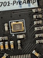
What do I need to modify in the 3E board? I need to remove the clock and then what?
I understand this crystal has 4 solder pads. To which I should solder the MCLK from the USB?
Also, can I reverse this if I solder it back again?
Attachments
I only have experience with the Zoudio V1 amp and a USB to I2S. I kept the wires short by locating the board close to the I2S connector pins on that amplifier. I got away with 1 ground wire, for the 3 signals; it was all I could do. Works, on two different amp instances with two different model USB to I2S boards.
Interesting 3E Audio has a finished product amplifier with the ADAU1701 inside. Analog in, or Digital via, you guessed it, BT. I wish someone would stick their neck out and pick, say, an 8 pin "
One would think it wouldnt be that hard... Certainly cheap enough.
Interesting 3E Audio has a finished product amplifier with the ADAU1701 inside. Analog in, or Digital via, you guessed it, BT. I wish someone would stick their neck out and pick, say, an 8 pin "
Panel Metal Mount Circular Metal Aviation Connector Adapter Male Female Plug Socket
" connector, arrange it G-S-G-S-G-S-G, put it in their product - so we can let the clutch out on a plug-able I2S connection between boxes.One would think it wouldnt be that hard... Certainly cheap enough.
https://www.diyaudio.com/community/...dsp-and-aliexpress.353836/page-3#post-6249732
Here is some info, but as I said before this is not a very practical configuration even though I did get it to work, you would be better of getting another DSP with an ASRC so the digital input can run on its own clock domain.
Here is some info, but as I said before this is not a very practical configuration even though I did get it to work, you would be better of getting another DSP with an ASRC so the digital input can run on its own clock domain.
https://www.diyaudio.com/community/...dsp-and-aliexpress.353836/page-3#post-6249732
Here is some info, but as I said before this is not a very practical configuration even though I did get it to work, you would be better of getting another DSP with an ASRC so the digital input can run on its own clock domain.
I do have an ADAU1452 from Aliexpress, but the build quality is much worse than 3E audio, besides it's much more advanced for me.
If the only caveats are 48kHz and to turn first the USB, then I think it's not the end of days, at least for me... Or at least I can give it a try.
Also, can't just use an external clock for both boards? The USB board has an 8mhz crystal and the DSP has a 12.2mhz crystal, so IDK if I can use the usb board's clock with the DSP
You can use the ADAU1452 board clock if you want to clock your dac from that same clock, or if you want to use ASRC in the ADAU1452 to reclock its output frequency to a reference clock signal from your dac. SQ should be best if you run ADAU1452 and your dac from the same clock, with it being one located on the dac board right next to the dac chip. A copy of that clock signal made by a clock buffer chip can then be sent to ADAU1452 to use as its reference clock. Again for best SQ, that same dac clock should be sent to the USB board to act as its clock. That way the whole system runs synchronously with the least jitter and distortion.
EDIT: Some other options are possible too depending on how you want to send digital audio from ADAU1452 to your dac. For example, if by way of SPDIF or TOSLINK, then that potentially raises some other considerations.
EDIT: Some other options are possible too depending on how you want to send digital audio from ADAU1452 to your dac. For example, if by way of SPDIF or TOSLINK, then that potentially raises some other considerations.
Thanks for your suggestion, but the idea is to use the ADAU1701 and hopefully get another input instead of the onbard ADC.You can use the ADAU1452 board clock if you want to clock your dac from that same clock, or if you want to use ASRC in the ADAU1452 to reclock its output frequency to a reference clock signal from your dac. SQ should be best if you run ADAU1452 and your dac from the same clock, with it being one located on the dac board right next to the dac chip. A copy of that clock signal made by a clock buffer chip can then be sent to ADAU1452 to use as its reference clock. Again for best SQ, that same dac clock should be sent to the USB board to act as its clock. That way the whole system runs synchronously with the least jitter and distortion.
EDIT: Some other options are possible too depending on how you want to send digital audio from ADAU1452 to your dac. For example, if by way of SPDIF or TOSLINK, then that potentially raises some other considerations.
I bought an USB to I2S in hope to use it, but there seems to be a problem with the clocks.
Because I can make my ADAU1701 work with my REFLEX USB to I2S board.Why do you say there is a problem with the clocks?
If I run the DSP as master I get a ton of noise and constant "pops". Tired TDM and I2S. Also tried REFLEX as master and DSP as slave but cant make it work.
Kipman suggested I need to feed MCLK from the REFLEX board to the DSP.
- Home
- Source & Line
- Digital Line Level
- USB to I2S for the 3e audio DSP board?