this is nothing more than power cathode followers...though you can call it any other way you like...
Figure 3.17(b) in the original post is not a 'cathode follower' in the traditional sense because it has voltage gain available to the full mu of the tube (depending on load).
The AC equivalent circuit of the common cathode circuit, and that circuit, is the same.
Only the definition of the polarity of the output signal is different (reversed).
Only the definition of the polarity of the output signal is different (reversed).
Right, and although the signal at the cathode is in phase with the grid, it is not a 'cathode follower' (in the usual sense) as suggested at post #18 because it has voltage gain. Again, plate at zero volts, B supply at cathode.
The 'upside down' cct is 'upside down' because the plate is referenced to zero volts and B supply connects to the cathode circuit (note the orientation of your drawing is incorrect.
To my understanding of the circuit, whether the supply voltage is positive on plate side or negative on cathode side does not define it as "upside down" since it doesn't matter as long as the voltage relationships are the same and the reason it's called "upside down" is because the signal comes from the cathode side but with gain, hence it is not a cathode follower. Notice referenced figure 3.17B uses a positive supply on the plate. But designers such as JC Morrison uses negative supply on cathode in order to achieve a fully direct-coupled circuit in singled-ended form without stacking positive supplies to an extremely high voltage. I was just wondering if a PP circuit can be achieved with a single winding secondary transformer because such item an be easily available from Jensen or Cinemag, etc... Apparently split secondaries are necessary.
By the way, TonyTecson was referring to the Cyclotron circuit as "power cathode follower" not the upside down in the first post. Separate topics.
"I was just wondering if a PP circuit can be achieved with a single winding secondary transformer because such item an be easily available from Jensen or Cinemag, etc... Apparently split secondaries are necessary."
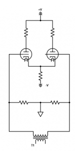
Only possibility is a diff amp with fixed bias on the grids, so one DC voltage source can be fed to both grids.
The drawing shows the source as ground, but it could be a DC voltage.
The two resistors must be equal to have equal, balanced AC voltages on the grids.
There could be a pot at the junction of the resistors (wiper to ground or DC voltage)
to balance the plate outputs by unbalancing the AC voltages on the grids.
Attachments
Last edited:
That's because it's actually the same circuit, with the load resistor split into two halves.
If you add the outputs of the two halves together, the total is the same as for the common cathode circuit.
I assume the output impedance of each phase bears the same concept, that is, divided by 2?
I know in a unity gain Split-Load circuit the two outputs' impedances combined is relatively low (learned that from SY's ImPasse preamp article) almost like that of a cathode follower, provided the loads are identical and simultaneous. Just curious what is the output impedance of the two phases in a split-load circuit with gain.
Since the circuit of post #2 is actually a modified common cathode circuit,
(no nfb loop) it behaves differently from the concertina circuit.
If we label each plate and cathode load resistor as RL (both being equal)
then the output impedance from either output node (both Zout are equal) is:
Zout = RL // (RL + rp)
or Zout = RL x (RL + rp) / (2RL + rp)
(no nfb loop) it behaves differently from the concertina circuit.
If we label each plate and cathode load resistor as RL (both being equal)
then the output impedance from either output node (both Zout are equal) is:
Zout = RL // (RL + rp)
or Zout = RL x (RL + rp) / (2RL + rp)
Last edited:
Another question I have about the upside-down circuit is that since the output is placed at the cathode, is the signal phase inverted or not inverted? Since all parameter is the same as a common cathode circuit, which inverts phase, one would assume the upside-down circuit inverts phase too but I suspect it does not. Because the bias still acts like like a normal tube so I assume it does not invert phase. I look forward to a reply. Thanks!
In post #2, the cathode output referred to ground is of the same polarity as the input.
This assumes that the transformer dots are both at the tops of the windings.
The plate output is in the opposite polarity of the input, referred to ground.
In the circuit of post #1 (fig. d), the cathode output relative to ground
is of the same polarity as the input. This assumes that the transformer dots
are both at the tops of the windings.
The signal in tube circuits at the cathode will always be of the same polarity as the grid signal
(both re ground), unless the grid or cathode is grounded, or some form of positive feedback is used.
Last edited:
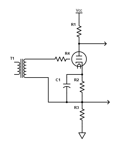
Use a concertina phase splitter. The single secondary goes between the grid and the junction
of the two resistors. No center tap or dual secondary needed.
If a split-load circuit like above is used as the input of an amp, how do you apply negative feedback taken from the output transformer's secondary? Do you use a blocking cap and resistor in series and connect them to the input grid with another resistor? Or you forgo that and apply symmetrically to the next PP or differential stage?
Overall feedback could go to a stage before the transformer.
Or to the bottom of the primary winding, if that is the input.
Or to the bottom of the primary winding, if that is the input.
Last edited:
cascode split-load & pentode split-load
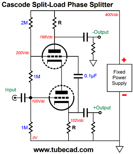
In the Broskie article, he shows a cascode split-load circuit in below 1st pciture (which shows an error of voltage at the plate of top tube and should be 298VDC, not 198VDC) and that got me thinking. I also drew up a different version in the 2nd drawing taking the voltage divider from the top tube plate instead of B+ so all current path goes from plates to cathodes.
The question is that is it possible to use a pentode in a split-load circuit? I know most pentodes' screen grid draws current which a split-load has to deal with in order be on the same current path. How can we use a pentode to replace the cascode in order to get more gain with an input transformer? Is the 3rd picture possible? How do you determine the screen voltage?
It should work, but probably not very well . . .
The plate load resistor can not be the same as the cathode load resistor.
That is because plate current does not equal cathode current.
And, if the screen current G2 varies at all with G1 signal (which it most likely will),
Then the required ratio of plate load resistor and cathode load resistor changes.
Nice idea, but might only work well with very small G1 signal voltages.
The above are just my opinions.
The plate load resistor can not be the same as the cathode load resistor.
That is because plate current does not equal cathode current.
And, if the screen current G2 varies at all with G1 signal (which it most likely will),
Then the required ratio of plate load resistor and cathode load resistor changes.
Thanks for the comment. I figured the screen current can rear its ugly head. And even if we regulated the screen voltage reference to ground the current can't pass through the cathode. I guess sticking to cascode is the better option since control grid does not draw current. I just thought common audio pentodes are cheap and they provide gobs of gain so it would be nice to exploit them in a single tube phase splitter. No free lunch.
- Home
- Amplifiers
- Tubes / Valves
- upside-down circuit in push-pull