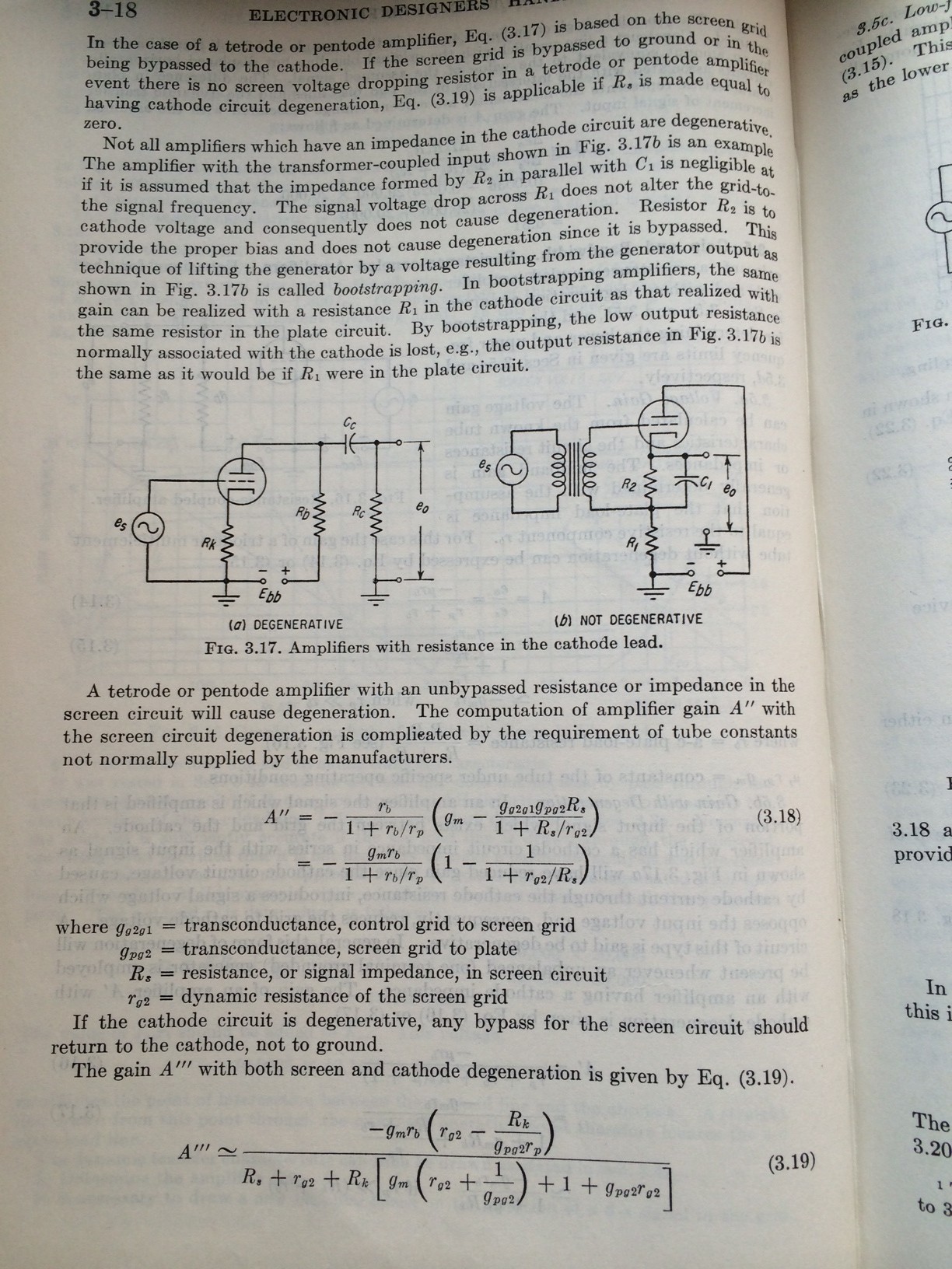
Can someone show me how to wire a push-pull version of the "upside-down" circuit (NOT a cathode follower) in figure-3.17B? It would be easy if the input transformer has split secondaries but what if you don't and not even a center tap? Is there a way to wire it in push-pull fashion and will it involve using two coupling caps connected to the cathodes or grids? I saw several single-ended designs and only one PP design that needs an input transformer with split secondaries.
I am not building an amplifier. I just want to understand it intellectually or how to apply or reconfigure it from SE to PP.

I am not building an amplifier. I just want to understand it intellectually or how to apply or reconfigure it from SE to PP.
Last edited:
Use a concertina phase splitter. The single secondary goes between the grid and the junction
of the two resistors. No center tap or dual secondary needed.
of the two resistors. No center tap or dual secondary needed.
Attachments

Last edited:
Thanks for the circuit, Rayma. Very simple and elegant, indeed. But a concertina/cathodyne/split-load circuit is not an upside-down circuit anymore and has different voltage points of the two phases and will be hard to make it direct-coupled to the next stage, say, two cathode followers.
Will this work? The two caps render the circuit not direct-coupled anymore, I know.

Will this work? The two caps render the circuit not direct-coupled anymore, I know.
Last edited:
By the way, a concertina/cathodyne/split-load has no gain so it would be better off just use the secondary as phase-splitter already. Concertina is the closest to a bridging transformer of 1:1 ratio.
This one has the the potential to leak DC current into the secondary if there's imbalance between the two cathodes.

This one has the the potential to leak DC current into the secondary if there's imbalance between the two cathodes.
Last edited:
You won't be able to make a practical direct coupled tube power amp, they've tried before.
Dual secondaries would be the way to go. That's no worse than one secondary in this case.
The circuit described as upside down just changes the ground reference point.
It works in the same way.
Dual secondaries would be the way to go. That's no worse than one secondary in this case.
The circuit described as upside down just changes the ground reference point.
It works in the same way.
Last edited:

By the way, a concertina/cathodyne/split-load has no gain
Actually the circuit in post #2 has normal voltage gain, split equally between the two load resistors.
That's the whole point of the topology. I used that circuit in the 70s, and it works well.
Last edited:
Actually the circuit in post #2 has normal voltage gain, split equally between the two load resistors.
That's the whole point of the topology. I used that circuit in the 70s, and it works well.
Ooh, it does?!! So say a 6J5 with a typical mu of 20, would one phase have gain of 10 and the other also 10?
This might give me ideas for other usage!
Last edited:
Whatever voltage gain the tube has in a common cathode circuit, split the plate resistor in two.
Each half becomes the top and bottom concertina load resistors.
Then the voltage gain at each output is half that for the single ended common cathode circuit.
The AC equivalent circuit is exactly the same for both circuits, only the reference point has shifted.
And they work exactly the same, same max total output (added together), same bandwidth.
Of course we can never get the full mu gain in most circuits, since the plate load is not >> rp.
More like mu/2 in most.
Last edited:
Of course we can never get the full mu gain in most circuits, since the plate load is not >> rp.
More like mu/2 in most.
So the gain is similar to a differential circuit using two tubes?
The fact it has gain inspires me to think of all kinds of circuit ideas! Thank you so much!
The gain at each of the "revised concertina" outputs is half that for a single ended, common cathode circuit.
If a common cathode circuit has a voltage gain of x14, then in this circuit each output will have a gain of x7.
That's because it's actually the same circuit, with the load resistor split into two halves.
If you add the outputs of the two halves together, the total is the same as for the common cathode circuit.
Last edited:
That's because it's actually the same circuit, with the load resistor split into two halves.
Got it! Thank you so much Rayma!
About a month ago I was asking the same question about the gain or lack of gain of the split-load circuit but in a different context. But by asking the question of an upside-down circuit with two tubes, I got my answer for a previous question! I'm excited about the possibilities. Thanks again!
The reason that the usual concertina circuit (with the input connected between the grid to ground)
has about unity gain, is that the lower output is included in a local nfb loop.
So the gain is about unity.
No such nfb loop exists when the secondary is returned to the lower output node, instead of ground.
So the gain is high.
A related situation was in the original Futterman amplifier, since the output drive signals were both
ground referenced, and they had to be unbalanced to work.
Last edited:
this is nothing more than power cathode followers...though you can call it any other way you like...
Last edited:
It would be easy if the input transformer has split secondaries but what if you don't and not even a center tap? Is there a way to wire it in push-pull fashion and will it involve using two coupling caps connected to the cathodes or grids? I saw several single-ended designs and only one PP design that needs an input transformer with split secondaries.
I am not building an amplifier. I just want to understand it intellectually or how to apply or reconfigure it from SE to PP.
The 'upside down' cct is 'upside down' because the plate is referenced to zero volts and B supply connects to the cathode circuit (note the orientation of your drawing is incorrect).
If you wanted a push pull 'upside down' circuit with an input transformer, the secondary would need to be split because there is no possible signal common at the secondary side of the transformer. Each 'return' is referenced to the cathode of the respective input tube and these cathodes are separated by the 'plate loads' to negative B supply.
I expect winding a transformer that is acceptable for this would be quite the challenge.
Last edited:
this is nothing more than power cathode followers...though you can call it any other way you like...
Audio Research used the cross coupled (all tube) driver circuit in their tube power amps in the 70s.
It was first used in the models Dual 100, Dual 50, and their modified Dyna Stereo 70.
And then it was used in all their other tube amps for years, including the D-150.
- Home
- Amplifiers
- Tubes / Valves
- upside-down circuit in push-pull