1)...my thoughts are... if the Orion engineers (see 3) were to assemble those boards today with the components available now, what would they choose?
2) Which is brought me to the thought of what op-amps would they then choose? Would they stick with the originals.
1) This all depends upon the selling price point, is it an "entry level" amplifier, or niche market amplifier..... Then what is its intended purpose, sound quality, or "we like the cars, the cars that go BOOM!!!"
2) See 1
3) What generation of engineers? Before ADST or when owned by ADST (my generation), or where they are now....
The LM4562 or LME49720 dual opamp has a higher power consumption then other opamps like 5532, which can cause power supply issues in car audio amps. I have made modifications to get the LM's work correct in some amps. And these LM's are >10 years old design..
So a drop in replacement...? no not always.
So a drop in replacement...? no not always.
IceFyre13th, to answer your questions:
A niche market amp. Intended purpose is sound quality. To be more specific...an Orion Xtreme 500.4.
As to the generation of engineers...ADST (your generation). You are definitely one of the perfect people for this conversation.
A niche market amp. Intended purpose is sound quality. To be more specific...an Orion Xtreme 500.4.
As to the generation of engineers...ADST (your generation). You are definitely one of the perfect people for this conversation.
Oh, c'mon! Opamps' current draw in an audio amp is 1/100th of what the power section draws! The difference between an NE5532 and an LM4562 is at most a coupla mA, and even 10 of 'em ain't gonna make a dweedle-watt's worth o' difference!!The LM4562 or LME49720 dual opamp has a higher power consumption then other opamps like 5532, which can cause power supply issues in car audio amps. I have made modifications to get the LM's work correct in some amps. And these LM's are >10 years old design..
So a drop in replacement...? no not always.
Different rails for opamps, like... almost always.
Many times the rails for opamps are supplied from a zener reference with series R that already runs HOT.
I think its worth thinking over current draw.... 😉
Many times the rails for opamps are supplied from a zener reference with series R that already runs HOT.
I think its worth thinking over current draw.... 😉
I'm sure that this has been stated (haven't followed closely) but... install sockets to check the various op-amps for strange behavior. You need to look at the output of the op-amp as well as listen to it.
Don't buy surplus sockets. I've purchased some that were old and wouldn't readily take solder, even thought they looked fine.
Don't buy surplus sockets. I've purchased some that were old and wouldn't readily take solder, even thought they looked fine.
Actually Perry no one did state that. Good advice. I always keep a bunch of those sockets on hand for whenever I have to replace an op-amp.
IceFyre13th, to answer your questions:
A niche market amp. Intended purpose is sound quality. To be more specific...an Orion Xtreme 500.4.
As to the generation of engineers...ADST (your generation). You are definitely one of the perfect people for this conversation.
Now my question is which heat-sink do you have? Hopefully the water pumper one (this is the black one that has the silver center and a stick on round Orion logo). Those two round "pipes" on the top fin were designed to be tapped for water nipple fittings.....not that we needed it, but for system buried in an area with no air flow it would be.
To start make sure the ground pin of the RCA jack is still connected (hated those things). Replace the electrolytic caps (wish we would of used poly caps, or similar in the signal path) in the signal path, and power supply (by now they are pretty dried up).
As to the op amps, Burr Brown OPA2604 replace the 5532, Burr Brown OPA627AP replace 5534's, and Burr Brown OPA4228 replace LM837 nicely and were the best IMHO....
You wont have any power supply issues with the Burr Brown replacements either.....
But as I said earlier, blind testing has shown most people cannot tell the difference at all....
I would look for Diamond Audio D5 / D6 600.4 or D6 5.2....the output stages of those were superior to just about anything back in the day....(where I went after ADST) if you are looking for SQ.
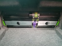
Funny you should mention water cooling those amps (see attached photo). Those are the amps I am currently running. They aren't the specific amps I was going to do this to but rather the same board, as I mentioned I have a couple brand new boards that were never populated...only have the resistors installed. I also have some new heat sinks of that same style.
Now that we've determined what op-amps...what, if any other component upgrades would you do?
Now that we've determined what op-amps...what, if any other component upgrades would you do?
Attachments
Myself, Elna electrolitcs. They have low ESR and in if the signal path get the audiophile grade.
Pots, you may not find anything that matches the PCB pattern, but using something of a better quality would not be a bad idea, even if remote mounted (use shielded wiring). Some of those multi ganged monstrosities had very poor tracking pot to pot. Better, once you know exactly where they are turned to, remove and measure the resistance from center to outside legs and replace with 1% resistors of the same value.....get those out of the signal path!!!
Transformer, add one turn to the secondary winding. Just one turn, its going to make a difference for headroom. Power supply FET's use IR's same part number. Output devices, the Motorola's always seemed to be the best....if you can find them. You may have to un-wind the original wire and replace the magnet wire with new, sometimes there was enough wire on the production transformers to add it without......sometimes. Don't be tempted to splice wire on.....its a recipe for disaster doing that.
Device to heatsink interface, mica and compound works great, better than the sil-pad. But you have to be careful to get those right and measure the tab to heatsink with a DMM to ensure there is no short......
Then when all said and done, run it with 4 ohm loads, not 2 ohms......sure less power over all, but it sounds better with an easier load.
I envy your build....lol....it's really one of those "what if's" that we all loved to experiment with....even though the results may not be that significant.
I still have a few "Engineering Builds" myself.........I kept a lot of my work from the day, have the first product I ever designed in an acrylic block.
Last edited:
Oh, boy, here we go with the car audiophool imaginary electronics!Transformer, add one turn to the secondary winding. Just one turn, its going to make a difference for headroom.
Then when all said and done, run it with 4 ohm loads, not 2 ohms......sure less power over all, but it sounds better with an easier load.
ONE turn of wire added to the power transformer secondary won't make DIDDLE-SQUAT's worth of difference.
An "easier load" has NOTHING to do with a power amplifier's sound, UNLESS it is NOT designed to run 2Ω loads.
And your back ground is........
One turn makes a few extra volts available to the regulation of the power supply output, it is not a lot and is still regulated by the power supply controller.....but it will not allow the power supply to sag below what was intended as some of the production units would exhibit.
Why, because the transformer core material, or winding's were not always built to spec....yeah they tried to save money and sometime it worked "good enough". Do you know how many times I unwound a production transformer, cut the core material only to find out the manufacture of said transformer shorted the turns, used on gauge smaller wire used an inferior core materiel.......too many to count.
So yes the extra turn wont make a lot of difference, but it does ensure the amp performed to spec as intended in its design.
And yes a 4 ohm load will have lower distortion measurements than a 2 ohm load, this is because the power supply is not working as hard to make power. So power supply ripple is lower and this makes the difference in THD measurements.....whether or not the difference can be heard is at best subjective.
As I said at the beginning of the discussion, changing op-amps is not going to make a hill of beans difference in what is heard during a double blind test....same goes for gold plated magna core special wire interconnects, or hockey puck quasi-magnalift turn table feet, or paper in oil capacitors with sheep skin insulation.
But, even .0001% less THD measured with .01 volts RMS more output is a measurable improvement......even if you cant hear the difference. THAT is what his build is about.....building the "Golden" amplifier.
Last edited:
THIS is the problem with 'upgrades' and why I've avoided this thread. It's more voodoo than anything else.
Different rails for opamps, like... almost always.
Many times the rails for opamps are supplied from a zener reference with series R that already runs HOT.
I think its worth thinking over current draw.... 😉
If the Zener is used as a shunt regulator (and is in regulation) then an op amp that draws more current will leave less current for the Zener to handle, so it will make the Zener run cooler and make no difference on the power dissipated by the dropping resistor. Leaving less for the Zener will raise the effective impedance of the diode, so the regulator will be more load sensitive, more signal will appear on the regulated rail.
Perry, I have to agree with you on "upgrades" normally I avoid doing so too. In this case since it is a basically an unpopulated brand new board, and that I can install "upgraded" components that will work together, I figured why not give it a try.
IceFyre13th, thank you for the additional information.
As to the pots...I'm going to be using this amp in full range stereo with 4 ohm loads as you suggested. Please correct me if I'm wrong... I was thinking I could install a jumper wire (in full stereo position) in place of stereo/high/low pass switches, thereby eliminating the need to install the high/low pass pots.
For the gain pots I was planning to either use better ones or as you suggested figuring exactly where they need to be turned to, remove and measure the resistance from center to outside legs and replace with 1% resistors of the same value.
As to the transformer. I currently don't have one for this amp and it is one of the more difficult components to locate. Could you possibly wind one as you were talking about for me? I would be happy to buy it from you.
I've been using Kapton MT to replace the sil-pad. Speaking of which my source for the Kapton MT tape dried up. Does anyone know where I can buy it with the adhesive on one side?
Its unlikely the original circuit skimped on op amps much so I suspect you will get little benefit from other op amps.
I had some recent experience in high speed op amps with a USB oscilloscope.
I noticed my square waves turning to sine waves at 500KHz+.
Yet my op amps were 3MHZ. Had same problem with a 10MHz op amp !
So, I did some research into it and 3MHZ is the small signal GBP.
It seems I need op amps with much higher slew rates to get the performance I need.
IceFyre13th, thank you for the additional information.
As to the pots...I'm going to be using this amp in full range stereo with 4 ohm loads as you suggested. Please correct me if I'm wrong... I was thinking I could install a jumper wire (in full stereo position) in place of stereo/high/low pass switches, thereby eliminating the need to install the high/low pass pots.
For the gain pots I was planning to either use better ones or as you suggested figuring exactly where they need to be turned to, remove and measure the resistance from center to outside legs and replace with 1% resistors of the same value.
As to the transformer. I currently don't have one for this amp and it is one of the more difficult components to locate. Could you possibly wind one as you were talking about for me? I would be happy to buy it from you.
I've been using Kapton MT to replace the sil-pad. Speaking of which my source for the Kapton MT tape dried up. Does anyone know where I can buy it with the adhesive on one side?
Yes you can by-pass the switches, and eliminate the cross-over pots if not needed (even cleaner...lol)
I have no cores, the most important part, to wind any transformers..sorry...best thing you could do there is find a "un-repairable" and harvest its transformer.
Yeah, thermal tape....but its better than nothing and you won't have to use thermal grease with it.......
Amazon.com: 3M 8805 1in X 5yd Thermally Conductive Adhesive Transfer Tape (1 Roll): Industrial & Scientific
I still like mica and grease best.
- Home
- General Interest
- Car Audio
- Upgrading the Op-amps in old Orion amps