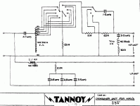
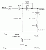
The first thing I recommend is separating the two halves of the crossover and feeding signal in via two sets of speaker terminals.
This allows you to either
bi-wire the speaker to amplifier connection.
or
to bi-amp the passive speakers
or
to single wire with a shorting link across the terminals.
I did this experiment after modifying my Berkleys about 30years ago, Alnico magnet.
It made, what I interpreted as, a big improvement.
I have never gone back to single wiring.
BTW,
only one PCB trace needs to be cut to allow the bi-wiring modification. You can revert to "normal" by soldering a wire across the cut.
Once you have this and decided which arrangement works for you, then you find which switch positions suit you.
That then allows you to "fix" the positions by permanently wiring the the switches out of circuit.
Last edited:
Thanks Andrew for the quick reply. Instead of modifying the original crossover, i am putting together a new set using sonic caps, mills resistors and foil inductors. Can you help with redraw the schematics for the "flat" position (this is how i listen at home and like it this way) and without the switches, Thanks again.
Join the Tannoy Yahoo group, everything you need to know can be found in its archives and if that is not enough someone will run you through what should be done.
The main thing other than bypassing the switches would be to hard-wire the xover rather than trying to pump all those watts through pcb traces and changing the caps.
Unlike Andrew bi-wiring is IME fairly pointless, especially in view of the other improvements which can be done to the standard Tannoy xover.
I hope you don't experience the massive deluge of spam I started getting soon after I joined that Yahoo Group.
It appeared they supply addresses to spammers, or have made their system accessible to spammers.
Fortunately, a big far eastern spam distributor got shut down a year or so back and that reduced my spam by about 90%.
It appeared they supply addresses to spammers, or have made their system accessible to spammers.
Fortunately, a big far eastern spam distributor got shut down a year or so back and that reduced my spam by about 90%.
Note that you have a tapped inductor in the treble circuit. Unless you normally listen on the second position from the bottom (green tap) it will be hard to duplicate the circuit response without this part. Also note that the bottom of the inductor goes to ground (black) although the drawing doesn't show it well.
Regards,
David S.
Regards,
David S.
I hope you don't experience the massive deluge of spam I started getting soon after I joined that Yahoo Group.
It appeared they supply addresses to spammers, or have made their system accessible to spammers.
Fortunately, a big far eastern spam distributor got shut down a year or so back and that reduced my spam by about 90%.
In the last 8 years I got less than 20 spams via that group, each by a phony member who all have been banned immediately.
Experiences may vary…
Note that you have a tapped inductor in the treble circuit. Unless you normally listen on the second position from the bottom (green tap) it will be hard to duplicate the circuit response without this part. Also note that the bottom of the inductor goes to ground (black) although the drawing doesn't show it well.
Regards,
David S.
Yes!!!
Do not damage the autoformer in any way or remove it from the circuit.
They are rarer than hens teeth and essential for the xover to function as planned.
I did not say via that group.
The coincidence of joining the Yahoo Group and shortly thereafter the massive increase in Spam was the jist of my comment.
An indication of the numbers.
Before joining I might get an average of 30 Spam Mails a month.
This jumped to 100 per day. Now swings around 10 a day and just very occasionally none in a day (Bliss !).
Wow, that's a lot of spam. I get 2 per day on average ever since I connected to the interweb, it never really changed to any noticeable degree.
Note that you have a tapped inductor in the treble circuit. Unless you normally listen on the second position from the bottom (green tap) it will be hard to duplicate the circuit response without this part. Also note that the bottom of the inductor goes to ground (black) although the drawing doesn't show it well.
Regards,
David S.
I guess I will have to stick with the original crossovers and just upgrade the parts then. Many thanks for the info. Save me lot of time doing research.
- Status
- Not open for further replies.
- Home
- Loudspeakers
- Multi-Way
- Upgrading crossovers for Tannoy HPD 385A

