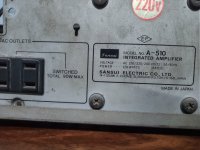
I have a Sansui A-510 Integrated Amplifier from the '80s. It uses a STK4843 dual op-amp that has failed. There are separate boards in the enclosure for the input selector, volume, tone control, power-amp, etc..., so I am considering just replacing the original power-amp board with a new one.
I have a bunch of LM3886 chips laying around, however I am not sure if it is safe to use them with the 27-0-27 transformer in the Sansui. According to this webpage, a 28V power supply will give an output of 38W * 2 = 76W, which is more than double the original 30W of the Sansui, thus I am unsure if the transformer can handle the extra power output.
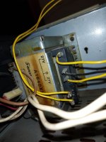
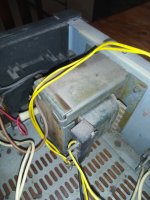
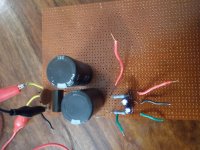
I have attached some pictures of the transformer. Please advise if it is sufficient to power two LM3886s.
I have a bunch of LM3886 chips laying around, however I am not sure if it is safe to use them with the 27-0-27 transformer in the Sansui. According to this webpage, a 28V power supply will give an output of 38W * 2 = 76W, which is more than double the original 30W of the Sansui, thus I am unsure if the transformer can handle the extra power output.
I have attached some pictures of the transformer. Please advise if it is sufficient to power two LM3886s.
Attachments
The original amplifier output clipped when it hit the voltage rails. The new LM3886 amplifier will do exactly the same thing. The power supply should be protected by the original fuse. I think it will work perfectly. I can't think of any problem.
Your 2x27Vac from the transformer will give 2x38-39Vdc when rectified. The maximum supply voltage for an LM3886 is +/-42V but Tom (Neurochrome) and other have indicated that the LM3886 is difficult to handle near maximum supply voltage. I assume stability problems. The page you refer to at Neurochrome indicates no higher than +/-35V.
The input power to the Sansui A-510 is max. 120W and almost all for the transformer. Let's assume that good 100VA is available from the transformer. That will take care of one LM3886 with 8 Ohm load. You want stereo and the music crest-factor is relevant.
If it was me, I would try. You anyway have the transformer. Only 8 Ohm speakers, nothing below. You may have some stability issues due to the rather high supply voltage. You can eventually reduce the voltage a bit with drop elements. At full throttle, the transformer may be hot.
Last edited:
I have been running my LM3886 amp at +/- 38.25 V DC for several years. It is my lab bench amplifier that gets abused. No stability issues. I run 4 and 8 ohm speakers and a few lower than 4 ohms, no problems yet.
Good to know from practical experience. With 4 Ohm, the transformer may be very hot if you play really loud. For normal use, no problems should be foreseen.
I liked the sound when running 38 volt rails. But could tell the LM3886 seemed to get hot even at low output levels. If driven hard they may fail soon.
The actual rail voltage varies depending on the power transformer and specs. Some list is unloaded output voltage. Others as voltage at rated current. Big difference.
The actual rail voltage varies depending on the power transformer and specs. Some list is unloaded output voltage. Others as voltage at rated current. Big difference.
If I understand correctly, the power supply of your amplifier still works. What dc voltages do you measure without the amplifier? Is the voltage selector set to 240 V?
Last edited:
The original amplifier output clipped when it hit the voltage rails. The new LM3886 amplifier will do exactly the same thing. The power supply should be protected by the original fuse. I think it will work perfectly. I can't think of any problem.
Good to hear. I was seeing many posts online stating that a transformer rated around 230VA should be used, so I was worried that the original transformer would not be sufficient.
it was me, I would try. You anyway have the transformer. Only 8 Ohm speakers, nothing below. You may have some stability issues due to the rather high supply voltage. You can eventually reduce the voltage a bit with drop elements. At full throttle, the transformer may be hot.
I am planning to use this amp with my 6 ohm speakers, and I also will need to use the original Sansui heatsink so I prefer to keep the power output lower.
If I understand correctly, the power supply of your amplifier still works. What dc voltages do you measure without the amplifier? Is the voltage selector set to 240 V?
The power supply circuit was on the original power amp board. Just yesterday, I desoldered the components and rebuilt just the power supply part on a perfboard. Have attached the schematic from the Sansui service manual (unfortunately it's not very clear). With voltage selector on 240V, I am getting the following voltages:
1) At A and B, before R1 and R2 - around +42 and -42V
2) At D and F, across the diodes - around +22 and -22V
The D and F outputs are for the phono preamp.
Would it be safe to power both the internal phono preamp and the two LM3886s from these outputs? What will be the power output?
I guess another option is adding another set of resistors on the rails along with R1 and R2? Maybe some trimpots?
Attachments
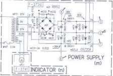
If you mean using the D and F power supply outputs for the LM3886 amplifier, it is clearly NO GOOD IDEA. I have problems reading the component values of R1 and R2 but when you use drop resistors and shunt zeners it is because you only have a very limited output current. It may be sufficient current for the phono preamp but it will be clearly insufficient for the LM3886 amplifier that will just pull the voltage down.
The +/- 42V outputs (A and B) will have to be used for the LM3886 amplifier but you can use some drop diodes before the big decoupling capacitors if you like less voltage. However, your +/- 42V is with no loading at all. With loading from the LM3886 amplifier, I guess you will be close to +/- 40V idle. Playing music on the amplifier will cause the voltages to drop another 2V.
Also for the big decoupling capacitors I have problems reading the value. I get the impression that the value is four digit and starting with "3". The total decoupling capacitance on each rail should be in the order of 10000uF. So, you should probably add some 4700uF (50V) on each supply rail.
Last edited:
Just bang in STK4913, bigger xfmr n resivoir caps
LM series is American produced monolithic and though streets ahead of class D is lacklustre to the serious STK chips
LM series is American produced monolithic and though streets ahead of class D is lacklustre to the serious STK chips
If you mean using the D and F power supply outputs for the LM3886 amplifier, it is clearly NO GOOD IDEA. I have problems reading the component values of R1 and R2 but when you use drop resistors and shunt zeners it is because you only have a very limited output current. It may be sufficient current for the phono preamp but it will be clearly insufficient for the LM3886 amplifier that will just pull the voltage down.
The +/- 42V outputs (A and B) will have to be used for the LM3886 amplifier but you can use some drop diodes before the big decoupling capacitors if you like less voltage. However, your +/- 42V is with no loading at all. With loading from the LM3886 amplifier, I guess you will be close to +/- 40V idle. Playing music on the amplifier will cause the voltages to drop another 2V.
Also for the big decoupling capacitors I have problems reading the value. I get the impression that the value is four digit and starting with "3". The total decoupling capacitance on each rail should be in the order of 10000uF. So, you should probably add some 4700uF (50V) on each supply rail.
Thanks for your advise.
If I understood correctly, the diodes can be connected in series where "A" and "B" outputs are marked on the schematic, is this right?
R1 and R2 are 6800 Ohms.
The big caps are 3900uF.
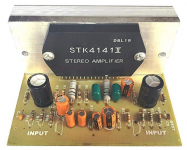
I also just picked up this cheap STK4141II board to try out in the Sansui with this power supply, until I get the time to build the LM3886s
Just bang in STK4913, bigger xfmr n resivoir caps
LM series is American produced monolithic and though streets ahead of class D is lacklustre to the serious STK chips
Maybe I will just stick with the STK if it sounds good! I noticed that there is a lot of praise online for LM3886, but not much information on the STKs.
Attachments
Last edited:
No, you put drop-diodes in series between the "+"-terminal of the bridge rectifier and the big cap for the positive rail. Similarly, between the "-"-terminal of the bridge rectifier and the big cap for the negative rail.
The idea is that they drop the voltage some 0.7V per diode, but as a bi-effect they will also add a little to the output impedance of the power supply. If you put the diodes as described above, they will only add impedance at low frequencies (and DC) and not disturb your higher frequency transients.
If you just add them at the "A" and "B" outputs, the diodes add impedance in the whole frequency range and may affect your transients.
3900uF, you better add 4700uF on both rails.
Last edited:
No, you put drop-diodes in series between the "+"-terminal of the bridge rectifier and the big cap for the positive rail. Similarly, between the "-"-terminal of the bridge rectifier and the big cap for the negative rail.
The idea is that they drop the voltage some 0.7V per diode, but as a bi-effect they will also add a little to the output impedance of the power supply. If you put the diodes as described above, they will only add impedance at low frequencies (and DC) and not disturb your higher frequency transients.
If you just add them at the "A" and "B" outputs, the diodes add impedance in the whole frequency range and may affect your transients.
3900uF, you better add 4700uF on both rails.
Thanks for clearing that up.
I have just ordered some larger caps to add on the rails.
Had a question about the STK board. I compared the circuit to the STK chip data-sheet, it is almost identical, but the data-sheet for the chip shows the negative sides of C5 and C6 connected to pins 1 & 18 respectively. However, on my board it is the other way around (positive sides are connected to the pins). Is this an error on the board or does the polarity not matter in this case?
Attachments
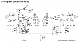
It's OK. C5 and C6 block dc. If the source that is connected to the inputs has no dc-offset, there will be zero voltage across C5 and C6 and their orientations do not matter. Most sources have no dc-offset on their outputs. 🙂
If a source has a dc offset, it usually is positive. Then the + of the capacitor should go towards the input.
Did you buy the STK chip through a reputable seller? Some versions are being counterfeit. A counterfeit STK chip poses a risk to your loudspeakers. Reputable sellers might have some new old stock.
Last edited:
It's OK. C5 and C6 block dc. If the source that is connected to the inputs has no dc-offset, there will be zero voltage across C5 and C6 and their orientations do not matter. Most sources have no dc-offset on their outputs. 🙂
If a source has a dc offset, it usually is positive. Then the + of the capacitor should go towards the input.
Did you buy the STK chip through a reputable seller? Some versions are being counterfeit. A counterfeit STK chip poses a risk to your loudspeakers. Reputable sellers might have some new old stock.
I bought the board off Amazon. It's definitely of dubious origin so I only plan to use it with my cheapo test speakers until I have the time to build a proper amp out of the LM3886s or a genuine STK ic... What is a good online source for genuine STKs?
Just bang in STK4913, bigger xfmr n resivoir caps
LM series is American produced monolithic and though streets ahead of class D is lacklustre to the serious STK chips
Who is/was the manufacturer of those STK's? I assume it was Sanyo? As they had to close their semiconductor division due to the 2004 tsunami, there aren't no genuine Sanyo STK devices available any more. And yes, Mouser doesn't list the STK4843 nor the 4913.
Best regards!
- Home
- Amplifiers
- Chip Amps
- "Upgrading" an old integrated amplifier - Power supply advise