The schematics below is from the CDP using 2xtda1543 with 12ax7 anode follow tube output.

The sound right out of the box is has sweet vocal but lacks PRAT and resolution / clarity. This is some steps I have done : -
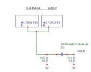
1. Replace the standard resistor with PRP and the capacitor as shown.
2. Snip treble kill cap C1
3. Run in the capacitors for 100hours.
After above changes, there is some improvement but needs improvement.
1. Can I know the local feedback changing / removing R4 and c3 will affect PRAT and resolution / clarity?
2. Why is the R7 R8 used since the IV is R6?
The sound right out of the box is has sweet vocal but lacks PRAT and resolution / clarity. This is some steps I have done : -
1. Replace the standard resistor with PRP and the capacitor as shown.
2. Snip treble kill cap C1
3. Run in the capacitors for 100hours.
After above changes, there is some improvement but needs improvement.
1. Can I know the local feedback changing / removing R4 and c3 will affect PRAT and resolution / clarity?
2. Why is the R7 R8 used since the IV is R6?
I need more clarity and resolution. I know jitter attenuation is another step but I just wonder if the existing circuit has some bottleneck at the tubes ?
The 12AX7 has a faulty workingpoint. With those figures it won´t work at all. Sure about the 12AX7A and the voltages?
If it could be changed to ECC88/6DJ8 things would be a lot easier to fix.
I guess the 1543s has a 5V supply. What is the DC-voltage at their outputs?
At least 5 components could be removed.
As it is now the whole arrangment looks like sh-t. But it can be helped though......
Below is what would work best with least effort. Beware the 2u/10k might soften lowend somewhat.
Attachments
Thks for your circuit.
The voltage measured at pin 8 and pin 6 is 3.3V. This voltage should be 2.3V ? or is this intentionally increased to reduce THD.
1 Can I know what is wrong the voltage level.
pls correct me if I am wrong. The voltage at AOR is 3.3V each. at zero signal, the steady current is 2x1.15 = 2.3mA. The voltage after the 680R IV resistor is therefore 2.3V * .68 = 1.56V.
with the 680R iv, the swing for full scale is 2x2.3mA = 4.6mA. This gives a swing of 4.6*0.68 = 3.12V peak to peak or 1.56V peak Voltage.
Since 1.56V is lower than cathode voltage which is 2.15V, the working condition is reverse bias.
2 I have difficulty to access the clock hidden in the transport mechanism. The transport is a KSS-213Q. Can I just reclock the signal going into BCK and apply the dynamic jitter attenuation.
3. what is the BCK frequency if this is in NOS mode. is it 2.8MHz or 1.4MHz.
ps. there is a cathode bypass capacitor which I have not shown.
Hey ccschua,
The voltage levels as you describe them are absolutely right at the 1543 outputs. From that you can see no gain is needed as 1Vrms is good enough for any amp. Zout will also be OK at ca 680ohms. The 12AX7 will probably have about the same.
If you check the Ua/Ia of a 12AX7 you will see the pathetic tube circuit won´t work, as the tube is at "turn-off" all the time. So the voltages you have given indicates it could be another tube, 12AU7???? To use a 12AX7 is anyway not a good thing due the tubes high mu at 100 and high Ri at over 60kohm.
There is no such thing as "reversed bias" as you have both a grid-leak, R5, and a coupling cap, C2, at the input. If you dump them it could be possible and also a good idea to arrange for it.
The voltage levels as you describe them are absolutely right at the 1543 outputs. From that you can see no gain is needed as 1Vrms is good enough for any amp. Zout will also be OK at ca 680ohms. The 12AX7 will probably have about the same.
If you check the Ua/Ia of a 12AX7 you will see the pathetic tube circuit won´t work, as the tube is at "turn-off" all the time. So the voltages you have given indicates it could be another tube, 12AU7???? To use a 12AX7 is anyway not a good thing due the tubes high mu at 100 and high Ri at over 60kohm.
Since 1.56V is lower than cathode voltage which is 2.15V, the working condition is reverse bias.
There is no such thing as "reversed bias" as you have both a grid-leak, R5, and a coupling cap, C2, at the input. If you dump them it could be possible and also a good idea to arrange for it.
This circuit is really out of ordinary. So far I guess the only system that uses 2 TDA1543. How odd. there is another 2 slot left but due to costs, it is not implemented.
The Vcc to the 1543 is using 8V. So the mid point is calculated to be 4.6V but actual experiment using oscilloscope shows the best mid point is 3.85V. I have 3.1V as the mid point. Should I bring it up but using a bigger IV or bigger Rref.
I recheck the tube and it is using 12AX7 and the Zero signal condition is still the same. kindly explain how not to operate in cut off.
I made a mistake in the R3 and it should be 100k.
The circuit is in fact working properly and sounds better with replacing the power bypass cap with blackgate.
Next mod on the list is the replacement of digital clock with 1ppm TCXO clock. However this need access to the CD mechanism with the receiver beneath it.
Can someone point me if the BCK should be 2.4Mhz (in DDDac circuit) or 1.2Mhz (in ECDesigns)?
revintage said:The 12AX7 has a faulty workingpoint. With those figures it won´t work at all. Sure about the 12AX7A and the voltages?
If it could be changed to ECC88/6DJ8 things would be a lot easier to fix.
Hi Lars, You are spot on. Please accept my apologies.
A called to the owner revealed it is indeed a 6922 but replaced with 12AU7. Just wonder what difference between 6922 and 12AU7. some seem to suggest 12AU7 over 6922. The 12AU7 is smoother and less glare than 6922.
Hi,
Why dont u go for SRPP? This is will greatly improve noise performance, which is extremely important for CD stage.
Secondly, even with 6922 the gain is too much. You can drop 680ohm I/V resistor to about 50 ohms which greatly unburdens the 1543.
Why dont u go for SRPP? This is will greatly improve noise performance, which is extremely important for CD stage.
Secondly, even with 6922 the gain is too much. You can drop 680ohm I/V resistor to about 50 ohms which greatly unburdens the 1543.
Hi,
see from the schematic, i think the output impedance is very high for the output stage,you should use cathode follower for low output impedance,so you will get better transparency and high freq response
cheers
see from the schematic, i think the output impedance is very high for the output stage,you should use cathode follower for low output impedance,so you will get better transparency and high freq response
cheers
- Status
- Not open for further replies.
- Home
- Source & Line
- Digital Line Level
- Upgrade TDA1543 tube output