White Dragon - you need to be careful when using alternate sources for even JEDEC-registered part types. For example, the ST flavor of 6284/6287 has drastically higher values for the bias resistors as compared to the Motorola/onsemi devices, making them unsuitable (read even slower) than the Motorola flavor. Not all TIP142/147s are created equal, either.
I sharpened my pencil and replaced the hot input nmos inputs with a pair of 2SK170s, biased at ~5 mA/side.
Forseen / predicted in post #16 above.
Yeah, but as I also mentioned in post 40, the THD results for the jfets were slightly inferior to the THD for the mosfet solution. I'm not all that concerned about the mosfet input capacitance (esp with cascode), and protection from ESD is relatively simple. The reslts for the J112 input diff stage were decidedly inferior to the 2SK170 or the nmos solution.
If I run the nmos differential stage without degeneration, I can get the THD down to 0.005%, no doubt due to the increased OL gain. The simulated harmonic profile is still good, with 5th and 7th down in the mud compared to 2nd order. I think this is the way I will proceed. The Zetex/Diodes inc mosfets are cheap and readily available compared to the possible n-jfet solutions, though I may try a J110 front end just to see what happens, esp as I'm cascoding the input stage anyway.
Edit - the J110s get me about the same simulated THD (without degeneration) as the 2SK170s, with similar simulated harmonic profile. This is biased at 10mA/side. Seeing as J110s are hard to come by these days (though I made a lucky score a few months ago), I''ll still stick with the nmos front end. You need a fairish pile of ZVN3306A for close matching, but they aren't all that expensive, esp as compared to the 2SK/LSK170. As a bonus, the E-line package is good for around 0.5W for a practical temperature rise, and they are easy to glue to one another with loaded epoxy (read JB Weld/JB Kwik) for thermal tracking. I have been laying in stock of both ZVN3306A and ZVP3306A, so I have enough of both hanging around to match up some differential pairs.
Edit - the J110s get me about the same simulated THD (without degeneration) as the 2SK170s, with similar simulated harmonic profile. This is biased at 10mA/side. Seeing as J110s are hard to come by these days (though I made a lucky score a few months ago), I''ll still stick with the nmos front end. You need a fairish pile of ZVN3306A for close matching, but they aren't all that expensive, esp as compared to the 2SK/LSK170. As a bonus, the E-line package is good for around 0.5W for a practical temperature rise, and they are easy to glue to one another with loaded epoxy (read JB Weld/JB Kwik) for thermal tracking. I have been laying in stock of both ZVN3306A and ZVP3306A, so I have enough of both hanging around to match up some differential pairs.
Last edited:
As long as the real parts are within 0.01% of the SPICE models, you can rely upon SPICE predictions of distortion.
So do I, easily enough for 2 channels worth. Keep in mind that you want the onsemi parts, as other vendors use much higher values for the internal biasing resistors than onsemi does.
BTW, I use the PSpice simulation for indication of whether an approach might be fruitful enough to proceed on the bench. It saves a fair amount of screwing around. I have 3 possible setups for THD measurement (HP8903A, Sound Technology meter, and a Pete Millett box and a good USB interface). I'll cross that particular bridge (maybe burn it, too) when I come to it. If all else fails, I have access to an AP setup at work, though that's not the friendliest instrument in the world in terms of user interface.
almost all Darlington's will use a basic
40 to 50 ohm resistor.
if you need some magic Darlington resistor
use a old high voltage package for a line switcher.
they will add a speed up diode and probably use
a 10 or 20 ohm resistor for the driver.
For a very very marginal improvement in fall time.
as with any basic diff amp.
you add a current mirror
and improve the second gain stage.
then you a have a zillion .008 to .001 %
amplifiers.
meaning at 12 Khz with a 4 ohm load.
same old .01 % distortion and the usual " sea of grass"
harmonic profile.
Last edited:
A lot of integrated Darlingtons don't use those low values for bias resistors - there lies the rub.
I'm not exactly responding to this troll bait, but in the sims I've done so far, 5th and 7th are 40 dB down and more compared to the 2nd. I am proceeding on this project as I see fit ,seeing as I am doing all the work. Tantrums will be ignored.
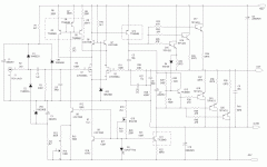
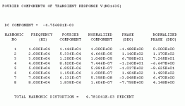
Here is the schematic I'll be using for the project. The adjustment for the supplemental current sources feeding the nmos input differential stage will allow one to adjust the output offset quite precisely. I will be looking at the first proto closely to see if there is any untoward drift in offset or output bias point. I expect there will be some initial drift that can be nulled out as the amp warms up. For this first rev, each output device is getting ~0.4A bias current. I'm thinking of laying out the board to fit a couple of double-flange Conrad heat sinks I have lying about. The board will probably also work well with one of the cases with heat sinks available in the Diyaudio store. The two 2200uF caps shown in the schematic are just local bypass - there will be plenty of uFs in the main cap bank feeding this thing. The design makes good use of available parts, though it's definitely more complex than the original design. I have the option to further crank up the bias point on the input nmos stage if I want to drive down the THD even more. At present, I'm running ~8 mA per side on the input diff stage. Simulated THD and harmonic content is shown in the accompanying output file. The results look encouraging enough to proceed, which is why I do initial sims in the first place.
Attachments
Last edited:
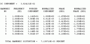
For people that want something closer to the original design, there's this. It does use 3 each of the TIP142G and TIP147G rather than the original Llambda Darlingtons. The sim performance doesn't look too bad, either.
Attachments
Can you layout your boards to fit the UMS? Would be super cool and make the design accessible to more builders... 🙂
https://cdn.shopify.com/s/files/1/1006/5046/files/universal-mounting-specification-v2.1.pdf
https://cdn.shopify.com/s/files/1/1006/5046/files/universal-mounting-specification-v2.1.pdf
I'll be watching this closely. Great Idea. I built and still us the A40 in my systems. My introduction to Pass Class A. Was and still is one of the best sounding amps I own. Like others said the originals are still available, I just ordered some. I also tried a version using a board available from Old Colony. I was using 142/147 but could never make it reliable. At power up outputs would randomly burn up. I tend to think they were counterfeits though. They were cheap. Anyway keep up the good work
So far, the onsemi TIP142G/147G looks like the best bet for this application, with a driver bias resistor of ~40 ohms. The values are higher on the ST version of the part (60ohms, NPN, 100 ohms, PNP). The original Texas Instrument version shows ~180 ohms for bias driver resistor. Since the TI part is also in the original TO-3P package, a TO-3 style insulating bushing would be needed on the mounting screw, something that may be hard to come by these days.
Freecrowder -
A disturbing propensity for blowing up seems to be a defining characteristic for the majority of fake parts. If you open up one of the suspects, you'll probably find a teensy die slathered with nasty white silicone goo. A lot of the time, the die won't even be capable of holding up to the voltage rating of the original part. Also, there's nothing to stop the counterfeiters from loading up the fake parts with defective die - more profit that way...
A disturbing propensity for blowing up seems to be a defining characteristic for the majority of fake parts. If you open up one of the suspects, you'll probably find a teensy die slathered with nasty white silicone goo. A lot of the time, the die won't even be capable of holding up to the voltage rating of the original part. Also, there's nothing to stop the counterfeiters from loading up the fake parts with defective die - more profit that way...
- Home
- Amplifiers
- Pass Labs
- Updated Pass A40 Design


