I've conducted internet searches and this is a rare amplifier. 1 in a 1000 compared to 1 in 90000 for a QUAD II. I'd love to make a stereo pair. Any ideas? Don't worry, I am not going to try switching on, any advice on bringing this all original back to life. New capacitors etc. Or don't touch and keep as museum piece.
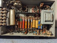
I'd be concerned that the lams and/or insulation on those transformers are compromised, though I've see worse that cleaned up okay. I'd remove both and test carefully for shorts with a variac. If they're okay, then if you can find a schematic you could restore it.
Build a mate? That's a different story. Without the original output transformer you might get close but not a perfect match by any means. ;-)
Build a mate? That's a different story. Without the original output transformer you might get close but not a perfect match by any means. ;-)
A friend of my father was the boss of the Dutch Quad import company. (Transtec) In the showroom I saw a Quad model 1, I cant'say it was identical but it had the same primitive look. Ik was mostly red .
View attachment 1160057
I've conducted internet searches and this is a rare amplifier. 1 in a 1000 compared to 1 in 90000 for a QUAD II. I'd love to make a stereo pair. Any ideas? Don't worry, I am not going to try switching on, any advice on bringing this all original back to life. New capacitors etc. Or don't touch and keep as museum piece.
The usual: replace any paper capacitors of which leakage can cause damage or danger, such as paper coupling capacitors in the output stage or paper capacitors that have to handle large DC or AC voltages. Check for wiring with damaged insulation, like dried out and cracked rubber, and replace it. After that and after following grovergardner's advice, try very slowly charging the power supply's electrolytic capacitors hoping to reform them, for example by removing all valves except tye mains rectifier and connecting a big resistor (100 kohm, 2 W or so) between the rectifier and the first electrolytic capacitor.

Seems like a good job I bought a Variac from the last audio jumble attended. So I have found a schematic. And taken a few more pics. Please forgive me but I am feeling a bit queasy at the thought of removing capacitors and transformers and losing originality. Couldn't I use the Variac and slowly raise the voltage. I'd also be confident to disconnect the preamplifier.
Still, turning this amplifier into an ornament also seems churlish after making such a find.
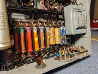
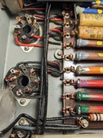
Using a fluke dmm I get .46uF and
.55uF across the two white caps on the tag strip.
Thank you for all your replies.
Still, turning this amplifier into an ornament also seems churlish after making such a find.
Using a fluke dmm I get .46uF and
.55uF across the two white caps on the tag strip.
Thank you for all your replies.
Attachments

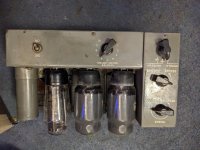
Well, I'll say this. The output transformer is impossible to replicate, mostly because of the cathode bias winding. Smoke that and it's a boat anchor.
At the very least, I would first take some resistance measurements on the transformers.
Remove all tubes. Measure the resistance between pins 4 and 6 of the rectifier sockets. Probably 100 ohms or something in the neighborhood. Measure resistance between pins 8 and 2 on the rectifier socket. It will be very small, like .6 ohms, but not a dead short.
Measure pins 3 to 3 on the output tube sockets. Maybe 300 ohms? Something like that. Measure pins 8 to ground on each output tube socket. Should be a bit more than 180 ohms.
Then you could test it on a variac without the rectifier and see if anything smokes. Take it up to like 80% and measure AC voltages on the rectifier plates (4 and 6). If all goes well, bring it up more to near 120 and measure the AC voltages.
If that goes well, add the rectifier and ramp it slowly up to 80% and see if you getv DC voltage from pin 8 to ground without smoke or issues.
If those wax-coated caps on the tag board really measure .47uF or greater they are waaaaay out of spec. I suspect maybe that reading is inaccurate.
The problem children are likely to be those 8uF/450v filter caps. But if you ramp it up slowly (like over many hours) on the variac and don't get smoke or excessive current draw, then it might just work.
If those 0.1 uF capacitors are paper capacitors and have really increased to 0.46 uF and 0.55 uF, they must have absorbed moisture (water has an epsilonR of about 80). Moisture also much increases their leakage, and as you can see in the schematic, any leakage increases the grid voltage of the output valves and, hence, the current through the output valves and through the output transformer. That could very well blow up the output valves or output transformer.
If they really are bad and you want to keep them in for originality's sake, you could connect another capacitor that doesn't leak in series.
You have a reasonable chance that the power electrolytics will work fine after very slow charging, and turning up the voltage very slowly with a variac is one way to do that.
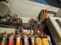
All valves removed. Rectifier pins 4&6, expected 100ohm, actual 255ohm; pins 8&2, expected .6 ohm, actual .5 falling rapidly to .1 Output tubes 3&3, expected 300, actual 127; pins 8&earth, expected 180, actual 330 though I have identified the 3W 180 and measured 199 across it. The internal wiring is impressive to me with a run of wires all piled up to make a neat wall.
I haven't got to starting the very gentle turning on as going to be away from the amplifier for a while. Thanks again for your insights and advice. Looking forward to updating progress shortly.
I haven't got to starting the very gentle turning on as going to be away from the amplifier for a while. Thanks again for your insights and advice. Looking forward to updating progress shortly.
Attachments
Those all seem close enough. The resistance of the output transformer primary seems low-ish but I don't know what the primary impedance is. Just a reminder to put a load resistor on the output and short the input before you try to fire it up.
I think this is a pretty risky proposition, I have restored a couple of Quad II as well as a variety of Leak stereo and mono amps in the now distant past and it was my recollection that every single coupling capacitor in all of those amplifiers were bad. The electrolytics in most cases were not too much better. I hear a lot of stories about successfully reforming electrolytic caps - this hasn't been my experience though.
You would need to go through and check the leakage of every single coupling cap at high voltage before I would recommend even "gentle" reforming with a variac. Use an incandescent lamp in series with the transformer primary - a 240V 100W lamp should provide adequate protection when the electrolytics short out, preventing destruction of the power transformer and other components.
Is it a museum piece - given the poor general condition I would say not really, or is it something with some utility to you? You have an option - leave all original and keep it as a conversation piece, or restore it which involves complete disassembly and replacement of most of the components. I had to do this to a pair of LEAK TL 50 Plus which was painful, but 25 years later they are still working.
Sowter may be able to make a fair facsimile of the original output transformer, might be worth build a pair from scratch. Put some nice looking dud valves in this one and put it in a display case. (?)
I disagree. 'Every single coupling capacitor' only amounts to two in this case. I've restored dozens of Quads without problem, and Leaks too. I do replace everything except the PSU caps, and those too if necessary.
I would guess that the output transformer isn't too different from the Quad II's, and Sowter, Majestic, and Quad themselves can supply that. But the readings you got seem OK. A Quad II OPT primary measures 120R and 180R of DCR from centre B+ tap to each plate respectively. The difference is accounted for by inner and outer winding causing different lengths for the same number of turns. Can you measure yours the same way?
The schematic seems almost identical to the Quad I from memory, and not too different from the Quad II, main differences being V1/2; the screen circuit; the return point of V4 grid and its Zobel network; and the B+ voltage of course.
I may have a schematic for the preamp, will check later today. But I suggest you don't use it.
Meridian Audio date this from 1949 but then they exhibit a receipt dated 1947. The Quad cathode winding feature dates back to 1943.
Two page schematic for QA12/P including the preamp is here: QA12/P PDF. Page 1 i the preamp; page 2 is the power amplifier, same as above. Apart from the phono stage the preamp is passive providing only passive tone controls and attenuation. As I said above I would not use it. One of the switch positions appears to accomplish that.
Ken Kessler's book gives the year of introduction as 1945.
Ken Kessler's book gives the year of introduction as 1945.
Last edited:
That's because you're also measuring the resistance of the cathode winding, U-V or W-V.pins 8&earth, expected 180, actual 330 though I have identified the 3W 180 and measured 199 across it.
- Home
- Amplifiers
- Tubes / Valves
- Unusual find. Acoustical manufacturing company QA12 with preamplifier