Hello,
I started trying to tune my first mono-amplifier combining the ZenV9 and the alephX designs.
I built 2 power supplies to get the negative VGS of the LU1014D. The main one is CLC and the second one is regulated with a circuit similar to the P1.7 PSU.
Most of the circuit seems to behave correctly compared with simulations and with Nelson's construction notes of the zenV9 ... but I have a problem with my "power" PSU.
The PSU is unstable, both negative and positive rails vary all the time by circa +/-50mV around +/-20.5V. The empty voltage is ~25V stable.
Do you have any idea to solve this problem ?
I have been stuck with this problem for a few days and I have no clue about the reason ?
the ground of the PSU is not linked to the "earth", can it be a reason ?
Thank you for your help.
Antoine
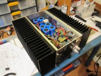
here is the schema of the PSU, the main board and a picture to make the problem more real :
I started trying to tune my first mono-amplifier combining the ZenV9 and the alephX designs.
I built 2 power supplies to get the negative VGS of the LU1014D. The main one is CLC and the second one is regulated with a circuit similar to the P1.7 PSU.
Most of the circuit seems to behave correctly compared with simulations and with Nelson's construction notes of the zenV9 ... but I have a problem with my "power" PSU.
The PSU is unstable, both negative and positive rails vary all the time by circa +/-50mV around +/-20.5V. The empty voltage is ~25V stable.
Do you have any idea to solve this problem ?
I have been stuck with this problem for a few days and I have no clue about the reason ?
the ground of the PSU is not linked to the "earth", can it be a reason ?
Thank you for your help.
Antoine
here is the schema of the PSU, the main board and a picture to make the problem more real :
Attachments
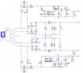

you don't need additional positive rail ;
you'll never have perfect tracking between main negative rail and additional negative rail ;
better use solution with CCS in parallel with drain resistor in LTP ( meaning each drain resistor have own dedicated CCS)
you'll still need that additional neg rail , but tracking problems are relaxed with dynamic nature of CCS
details buried somewhere in Aleph J thread - search for EUVL's solution
Hi Zen,
Thank you for your reply.
1- I agree that the extra positive rail is not necessary but I initialy planned this additionnal rail, thinking that a regulated supply for the imput stage would not be bad for the amp.
2- I recently discovered the thread dealing with the LU Vgs issue, describing the idea of a CLD in parallel with the drain resistor in LTP. But I had made my design and my PCB before I discovered this thread. In addition, I noticed that Nelson had proposed an alternative solution consisting in asserving the -- rail with the - rail to match the ripple in both rail, what I tried to implement with the extra 1000uF and 50R between negative rails.
It is maybe not the best solution but do you think that it can lead to the unstability of the main PSU (both negative and positive rail fluctuate) ?
Antoine
in any case - you must ensure that neg rail and additional negative rel are firmly tight ; regulate that additional rail "against" main negative rail , not gnd
that way they'll "float simultaneously"
that way they'll "float simultaneously"
in any case - you must ensure that neg rail and additional negative rel are firmly tight ; regulate that additional rail "against" main negative rail , not gnd
that way they'll "float simultaneously"
Hi Zen,
The good news :
I increased (actually decreased) my additionnal negative rail and I regulate it with a simple lm7905 with the negative rail as reference and it works.
The PSU is stable, the offsets can be trimmed...and this first amp sings.
Thank you for your help.
The bad news :
The amp do not present any humm...but...
My preamp (clone of P1.7 + xono) is noisy : there is a buzz, mainly at high frequency, which is not depending on the volume...
Do you think there is a ground loop
Antoine
possible
how you organized grounds (especially vs. safety ground ) in both - amp and preamp ?
The same in the amp and preamp :
- "signal" grounds are not connected to the "safety ground" from IEC.
- the "safety ground" from IEC is connected to the chassis (made of aluminium)
I'll check that there is no shortcuts between chassis and grounds in the preamp
you must connect at least one ( either in amp or preamp ) signal gnd to safety GND
best is to connect audio gnd to safety gnd in each
make that in Papa's way - through 10R-30R NTC ; not tiny one ; he use CL60
best is to connect audio gnd to safety gnd in each
make that in Papa's way - through 10R-30R NTC ; not tiny one ; he use CL60
you must connect at least one ( either in amp or preamp ) signal gnd to safety GND
best is to connect audio gnd to safety gnd in each
make that in Papa's way - through 10R-30R NTC ; not tiny one ; he use CL60
Thanks for the advise,
I'll try to find this big NTCs.
There is no one in my amps because I did not manage to find it. No doubt that I would have done as Papa does if I could find some of them...
Start-up issue
Hello every one
I have a new issue, 10 years after first turn on and normal behaviour.
One of my amp is making a pretty loud "ZIP" buzz (mostly audible high frequency) at turn on.
It lasts a couple of minute during warm up until it get back to normal noise level.
This noise is loud enough at start up so that I can't let the speaker wired...I just make short test until it stops.
After the amp runs as usual
Any idea of the faulty parts, caps... ???
FYI the PSU and main circuit are in first page except one trick made following ZenMod comments on VGS: one +/-5V regulator between the 2 PSU to have the a stable VGS jfet ?
Best regards
Last edited:
- Home
- Amplifiers
- Pass Labs
- unstable PSU for aleph-x à la ZenV9