Greetings -
I'm mostly a lurker on this forum, as I don't have much to add over and above the wisdom that the frequent posters display, but it's been an education to hang out here.
I've been working on my old Eico HF-87 and I'm trying to restore it to the original topology. I've had this amp since I was a kid in the 60's and it's been through several iterations of mods, including the most recent FET driver board setup. Now, it's back to the original schematic with pretty much all the same resistor values and the following changes:
- CLC power supply with much bigger caps, and polypropylene bypasses
- polypropylene caps throughout the signal path, generally larger values, mostly a step or two up in standard values.
- fixed bias on the output tubes with a 10 ohm resistor from each cathode to ground
- removed the level controls on the input
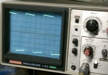
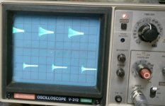
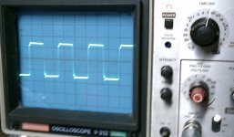
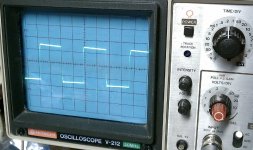
I don't think any of these things should make the amp less stable, but it is. Open loop, the amp will output a pretty good square wave with no sign of instability. Add the 7.5K feedback resistor/cap and it starts ringing. I've attached pics of a scope display of both. The "no feedback" picture is taken just after it starts ringing, turning up the 1.2 khz input signal makes the ringing much worse.
The feedback rolloff cap is a 200pf polystyrene. After reading the forum a bit, I added a 100 ohm screen grid resistor, then replaced that with a 1K ohm screen grid resistor, hoping that would tame the oscillation. Not much difference. Both channels are the same, so I doubt it's a wiring error, but I did try to trace everything just to make sure.
I'm hoping the brain trust on the forum will have some suggestions. I don't think I'm missing anything simple.
Thanks,
Jim
I'm mostly a lurker on this forum, as I don't have much to add over and above the wisdom that the frequent posters display, but it's been an education to hang out here.
I've been working on my old Eico HF-87 and I'm trying to restore it to the original topology. I've had this amp since I was a kid in the 60's and it's been through several iterations of mods, including the most recent FET driver board setup. Now, it's back to the original schematic with pretty much all the same resistor values and the following changes:
- CLC power supply with much bigger caps, and polypropylene bypasses
- polypropylene caps throughout the signal path, generally larger values, mostly a step or two up in standard values.
- fixed bias on the output tubes with a 10 ohm resistor from each cathode to ground
- removed the level controls on the input
I don't think any of these things should make the amp less stable, but it is. Open loop, the amp will output a pretty good square wave with no sign of instability. Add the 7.5K feedback resistor/cap and it starts ringing. I've attached pics of a scope display of both. The "no feedback" picture is taken just after it starts ringing, turning up the 1.2 khz input signal makes the ringing much worse.
The feedback rolloff cap is a 200pf polystyrene. After reading the forum a bit, I added a 100 ohm screen grid resistor, then replaced that with a 1K ohm screen grid resistor, hoping that would tame the oscillation. Not much difference. Both channels are the same, so I doubt it's a wiring error, but I did try to trace everything just to make sure.
I'm hoping the brain trust on the forum will have some suggestions. I don't think I'm missing anything simple.
Thanks,
Jim
Attachments
A few thoughts...
It doesn't seem real far from stable...Maybe we could do an experiment to see just how far...
If you inserted another 7.5K resistor between the 16 Ohm tap and the 7.5K||225pF, you would drop the loop gain by 6 dB, and increase the amp's gain by the same amount. The decrease in loop gain might be enough to get you out of trouble...you could then sweep the amp for frequency response to see where the big rise is, and that would probably give us a good hint as to what might be going on.
Just some random thoughts...have you checked C12 and C17 (careful...lots of volts)?
Is your R16/R30 replacement wirewound? Might it be resonating and doing something funny? Are any of the new resistors wirewound? extra inductance could casue a problem.
The asymmetry is the clue- your problem originates in the output transformer. The ones used in the HF87 were generously proportioned but not particularly well-balanced. C12 could be suspect or you might need to increase its value a bit. You might also try a step network across R9.
Increasing the feedback resistance and with it, the gain, seems to help. I'd really like to go the other way though as the amp had too much gain from the factory. My original goal was to increase the feedback and reduce both the input sensitivity and (at least theoretically) distortion.
All resistors are metal film. C12/C17 are brand new polyprops, and I have the same problem on both channels so I'm guessing it's not the cap. I could lift one end and test it. But the fact that these caps are connected to one side of the transformer primary - couldn't that be the source of the asymmetry? R16/R30 have each been replaced by two 10 ohm resistors which should be metal film from each cathode to ground. (adjustable bias via a separate supply)
As far as frequency response, I could test that. The oscillation is way up there, I think around 200Khz if I remember correctly. I'd be surprised if the amp was still producing useful output up there, but I don't know.
"step network"? Could you elaborate on that?
I'll reduce the feedback and look at the frequency response. BTW - increasing the input signal voltage makes it less stable. At some point the entire top half of the square wave is just high frequency ringing, with the feedback resistor.
Thanks,
Jim
Last edited:
Couldn't wait until tomorrow, so I just did some poking around with the scope. With a sine wave, the amp looks pretty stable up to about 2.2v P-P out, after which it will start ringing on the tops of the waves. I did a sweep with my audio generator and indeed there is a pretty big peak around 91Khz, where the gain is up by 2.5x or so. The amp was flat to past 80Khz - didn't think that was possible on old tube stuff. So is it just a case of rolling the open loop gain off at some reasonable frequency - say 30Khz? And if so, where's the best place to do that? Is that going to increase the distortion at the high end? (less open loop gain -> less feedback)
Jim
Jim
Last edited:
Ideally...
You could measure the loop gain, or maybe just open the loop entirely, and measure the gain and phase. Then you could figure out just what the feedback could look like to be stable.
That it only happens at higher levels is sensible...output tube gain increases with plate current, increasing loop gain.
I've moved this thread for you.
By "step network," I mean a series resistor and capacitor, with the series combination put in parallel with the plate load resistor. It's called a step network because it causes a step in the frequency response at a point determined by the RC combination.
In this case, trying to reduce the overall feedback to stabilize things won't address the fundamental problem, the output transformer asymmetry. The step network (and for that matter, the cap across half of the output transformer primary) reduces the feedback on only the side of the push-pull that needs it. I'd still replace C12 first (watch the voltage rating!), and if that doesn't help, perhaps increase its value. if THAT doesn't work, go for a step network, which should be adjusted while watching the square wave response.
I agree with Sy, you have a high frequency oscillation. If you sweep your sine wave above the audio band, I bet you see the gain go up at high frequencies right before it drops. The phase compensation circuit that SY described will squash that flatter than a pancake. It will be something along the lines of 15K resistor and say a 270pF cap in series with the voltage amp plate load resistor. The values will be a good starting point (in my experience), and then tuned by eye using a scope. You could also do a bode plot, but that seems painful vs. tweaking it by eye.
Sheldon
Sheldon
As suggested by djoffe, check C12 and C17. The real Eico manual has those at 750pf rather than the 470pf on your Sams schematic.
Tweaking in a Step Network
Here's a procedure to use...
Place a series RC from the plate of V1 to ground. In round numbers, the ECC83 at this operating point has gm=1 milliSiemen and go=0.01 milliSiemen. To stop the oscillator, you probably want to drop the gain by about 12 dB.
That means you'd start with the R of the RC at about 15K, with C chosen at 0.01 uF...don't worry...it's just a starting point. Make sure that this network is adequate to stabilize the amp to your liking.
Now, if the amp is still a bit unstable, then decrease the R. If you think it's too stable, e.g. you're throwing away too much gain, then increase the R until you are happy with the gain stability trade-off (maybe make it a bit more stable than you feel is warranted).
Finally, decrease the C as you test stability. The smaller the C, the more forward gain that will remain in the audio band to help suppress distortion.
Just as a wild back of the envelope guess, you might end up with an R of about 33K and a C of about 100 pF.
Please report back on your results, and don't get bit by the HV.
There is another way to look at all of this.. Look at opportunities to reduce the amplifier's open loop gain, I think that slogging instability with a dominant pole at very low frequencies due to excessive global feedback sounds really bad. Redesign the front end to use a lower mu triode, use local (current) feedback as applicable.
The original design was probably stable at the design feedback levels - when you reduced the closed loop gain by 6dB or so you probably needed to move the dominant compensation pole lower by at least an octave or so - this actually can result in pretty lousy open loop linearity for anything but sinewave test signals.
Not withstanding the mentioned flaws in the OPTs, they are actually pretty good as small amp PP OPTs go. (edit: removed integrated - what was I thinking.. 😀 )
Last edited:
HF87 was a power amp, not an integrated. The OPTs are about the size of A431s, very generous for the nominal 35W amp rating. I've restored several of them (have one in the queue at the moment).
Thanks for all the help on this, I've gotten a lot smarter on something that apparently isn't uncommon. Here's the results of some reading and a couple of hours at the bench.
Gain measurements
no loop feedback @ 16v P-P out -> Av=51.6/34dB
w/ 7.5K & 200pf feedback loop -> Av=213/46.6dB
If I've got this right, 13dB doesn't seem like a lot of feedback.
vintage sound caught this:
"check C12 and C17. The real Eico manual has those at 750pf rather than the 470pf on your Sams schematic."
Indeed - good catch. I took the 470pf from the other channel and first put it from B+ to the other side of the transformer and it didn't make much difference, so I paralleled it with the first cap to make 940pf and it tamed things down a bunch.
After reading about feedback and stability in a bunch of places like
http://www.tubebooks.org/file_downloads/moyle_amp.pdf
I decided to see if I could reduce feedback by adding some local feedback and reducing open loop gain. So I "cathode coupled" (not sure if this is the right terminology) the 10 ohm cathode resistors through the transformer secondarys, connecting them to the G and 32 ohm taps and grounding the 8 ohm tap for the DC return. This reduced the gain Av=133/42.5dB. The amp was now stable up to clipping on a square wave with some overshoot. I think this should add some linearity to the output stage as well as reduce the output impedance through the local feedback.
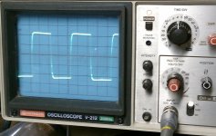
Finally, per Sy's suggestion of a step network, I put a 9K/470pf cap series combination - scientifically chosen since it was the only suitable cap I had in my cap box - from the plate to ground. Bingo! It's stable to clipping with a square wave, even overdriven well past clipping. A pic is attached, outputting about 50V P-P @ ~1.2Khz into 7.5 ohms - that's 83 watts of square wave... I'll get a stock of low value caps and reduce the value until it starts to ring again
The amp clips a sine wave at about 17.7VRMS into 7.5 ohms, for about 40 watts. Seems to be more or less flat at full power from 20-20khz.
I need some more parts so I can clean it up and start listening to it! I don't get sentimental about hardware or cars, but I'm really excited about getting this thing going again. It's been with me for four decades - since I was about fourteen. Now if I can just find my Led Zepplin II album I'll be set.
Thanks to everybody for all the help on this. I'll post again after I've had a chance to get some listening time in.
Jim
Gain measurements
no loop feedback @ 16v P-P out -> Av=51.6/34dB
w/ 7.5K & 200pf feedback loop -> Av=213/46.6dB
If I've got this right, 13dB doesn't seem like a lot of feedback.
vintage sound caught this:
"check C12 and C17. The real Eico manual has those at 750pf rather than the 470pf on your Sams schematic."
Indeed - good catch. I took the 470pf from the other channel and first put it from B+ to the other side of the transformer and it didn't make much difference, so I paralleled it with the first cap to make 940pf and it tamed things down a bunch.
After reading about feedback and stability in a bunch of places like
http://www.tubebooks.org/file_downloads/moyle_amp.pdf
I decided to see if I could reduce feedback by adding some local feedback and reducing open loop gain. So I "cathode coupled" (not sure if this is the right terminology) the 10 ohm cathode resistors through the transformer secondarys, connecting them to the G and 32 ohm taps and grounding the 8 ohm tap for the DC return. This reduced the gain Av=133/42.5dB. The amp was now stable up to clipping on a square wave with some overshoot. I think this should add some linearity to the output stage as well as reduce the output impedance through the local feedback.
Finally, per Sy's suggestion of a step network, I put a 9K/470pf cap series combination - scientifically chosen since it was the only suitable cap I had in my cap box - from the plate to ground. Bingo! It's stable to clipping with a square wave, even overdriven well past clipping. A pic is attached, outputting about 50V P-P @ ~1.2Khz into 7.5 ohms - that's 83 watts of square wave... I'll get a stock of low value caps and reduce the value until it starts to ring again
The amp clips a sine wave at about 17.7VRMS into 7.5 ohms, for about 40 watts. Seems to be more or less flat at full power from 20-20khz.
I need some more parts so I can clean it up and start listening to it! I don't get sentimental about hardware or cars, but I'm really excited about getting this thing going again. It's been with me for four decades - since I was about fourteen. Now if I can just find my Led Zepplin II album I'll be set.
Thanks to everybody for all the help on this. I'll post again after I've had a chance to get some listening time in.
Jim
Attachments
The packages from Digikey and Newark came in and I had a chance to tinker tonight. The end configuration is the result of a bunch of different suggestions from this thead and some reading of various forum stuff. What I ended up with is this:
- Put a 750pf cap from the plate on one output to B+ per the Eico schematic, not the 470pf as in the Sams schematic
- Tinkered with feedback caps and settled on a 220pf polystyrene, no change in value
- Coupled the EL-34 output cathodes through 10 ohm resistors and the secondary of the transformer to put some local feedback on the output stage and reduce overall gain.
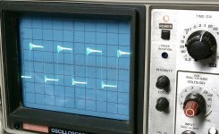
- Added a 10K/200pf step network. Started with 10K 33pf and worked up to 200pf.
Pics below of No step network/10K+150pf/10K+200pf. I think the 200pf looks best. The 470pf in the previous post seems a little too rounded, but I'm not sure what will work best in the real world. (Any opinions?)
I've got to travel for a couple of weeks so I don't get to listen to it for a while, but after I clean up the mess I made of my neat rebuild, I'll drop the amp in my system, put a scope on it, and see how it sounds. The speakers are KEF C80's which have an absurdly complex crossover and lots of reactance so it will be interesting to see how it behaves in the real world. Unfortunately, I can't run square waves through the KEF's to assess the stability of the amp.
Thanks for all the help guys, this would have been a tough task otherwise.
Jim
- Put a 750pf cap from the plate on one output to B+ per the Eico schematic, not the 470pf as in the Sams schematic
- Tinkered with feedback caps and settled on a 220pf polystyrene, no change in value
- Coupled the EL-34 output cathodes through 10 ohm resistors and the secondary of the transformer to put some local feedback on the output stage and reduce overall gain.
- Added a 10K/200pf step network. Started with 10K 33pf and worked up to 200pf.
Pics below of No step network/10K+150pf/10K+200pf. I think the 200pf looks best. The 470pf in the previous post seems a little too rounded, but I'm not sure what will work best in the real world. (Any opinions?)
I've got to travel for a couple of weeks so I don't get to listen to it for a while, but after I clean up the mess I made of my neat rebuild, I'll drop the amp in my system, put a scope on it, and see how it sounds. The speakers are KEF C80's which have an absurdly complex crossover and lots of reactance so it will be interesting to see how it behaves in the real world. Unfortunately, I can't run square waves through the KEF's to assess the stability of the amp.
Thanks for all the help guys, this would have been a tough task otherwise.
Jim
Attachments
Last edited:
You might try playing with the R value in the step network. If you can rig up a potentiometer with an insulted knob, it's easy to determine the right value in just a few minutes. Otherwise, move it up and down a bit with both cap values to see where the square wave looks best. Then put a couple of microfarads across the load resistor to make sure that the amp doesn't oscillate- the square wave won't look as pretty since a tube amp's source impedance tends to be high, but any ringing should be exponentially damped.
- Status
- Not open for further replies.
- Home
- Amplifiers
- Tubes / Valves
- Unstable Eico HF-87