Is it possible to do something like a parrellel or bridged setup, with 2 IC's for example per channel. But, feed each IC a different band of frequencies.
Like the following setup:
Have an active filter on the input that splits the frequncies @ 24 db at about 500Hz or 100Hz, this way you would have one IC doing alot of the hard work and another dedicated to the more subtle range, then if lets say the bass starts kicking in, the highs don't suffer.
I know what your thinking, why not just have two inputs on the speaker and do a bi-amp setup, and all though thats the better setup, it's not as daily or practical of a design that everyone can take advantage of.
I figure the frequencies would not be a problem, since there would only be cancellation or additives at the crossover point, which is no different than most passive crossovers in speakers. But the other thing, actually the only thing that has me worried is how the amplifiers will react being tied to each. Can the output of one mess up the other? And I'm gonna try and not sound retarded but you could put a diode on the output, so that voltage can't enter back into IC right? But on the parellel and bridged version, the IC's output are tied to a common connection, but they are producing the same sine wave, either in phase or out of phase. I know you would also have to match there outputs, obviously.
I hope you understand what I'm explaining, and I'm sure I'm not the first person to ever come up with this idea. But if you don't understand I can and try and explain better. I would attach a drawning of what I mean, but these computers at school have some nice restrictions on them (IE, only internet explorer works 🙁 ).
You can't do it like that. Half of the time one amp will source current and the other will sink it (bypassing the speakers) causing them both to go into shutdown / meltdown. No you can't put a diode on the output because audio is made up of AC signals and you would effectively stop 1/2 of the signal getting out of the amp ... not to mention that the amp would be almost unloaded for half of the signal.
You can split the freq bands over several amp channels, and combine at the outputs. The only advantage I see is that you have less problems with intermodulation between different frequencies (generating sum- and differences between different freqs). My gut feeling is that to really have advantages is that you would need much more than just two bands, like 10-100Hz, 100-1000Hz, 1k to 10k and > 10k.
The efffort may not be worth the (subtle?) advantages, and may introduce new problems that were not there before (like phase shifts between bands).
Jan Didden
The efffort may not be worth the (subtle?) advantages, and may introduce new problems that were not there before (like phase shifts between bands).
Jan Didden
Just bi-amp and set the filters at the input, most of the time its nothing but a simple r/c circuit anyway.
ron
ron
AudioFreak said:You can't do it like that. Half of the time one amp will source current and the other will sink it (bypassing the speakers) causing them both to go into shutdown / meltdown. No you can't put a diode on the output because audio is made up of AC signals and you would effectively stop 1/2 of the signal getting out of the amp ... not to mention that the amp would be almost unloaded for half of the signal.
So why do regular bridged/parrellel amps function fine? Of course I skipped over that diode part, but you could put one for the negative and positive parts of the wave right???
The only advantage that I was trying to push was that one chip would be doing the hard (bass) work while the other amp was doing the less tedious stuff (like everything above). This way the bass chip can do its job and the high freq chip can run cool.
Like I said a bi-amp setup is the obvious winner here, but this is supposed to work with all speakers, and most speakers don't have bi-amp inputs.
Is there a device that could act as a gate of sorts? like maybe an output opamp, that both signals would feed into and emerge as a single output. But the device it self would just be passing the signal, not actually amplifying the signal.
Like a twin turbo setup, you got a small one that spools at normal RPM ranges, and than the big momma that spools in the mid to high to pick up where the effeciency of the smaller one is diminishing. Even though they both feed the same engine.
Heres an attachment of what I mean....
Attachments
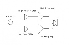
As far as I can see, you would need a circuit after the amps and before the speakers to mix the 2 signals together.
Bridged/Parallel amps work fine because all the outputs that are in parallel with each other output the same signal and so dont really fight each other much.
Bridged/Parallel amps work fine because all the outputs that are in parallel with each other output the same signal and so dont really fight each other much.
Hybrid fourdoor said:The only advantage that I was trying to push was that one chip would be doing the hard (bass) work while the other amp was doing the less tedious stuff (like everything above). This way the bass chip can do its job and the high freq chip can run cool.
It will work, with a slight modification. Amps tend to have very low output impedance. So if you simply parallel two amps together, one of them will be driving the other - this is true for simple paralleling or paralleling with active cross-over. So you have to introduce some output impedance to the amps. That is usually done via a small, like 0.5ohm, resistor in serial with each amp and then sum them together. The National application note should have an example of that.
Simplying tying the output pins together will cause major blown-out.
AudioFreak said:As far as I can see, you would need a circuit after the amps and before the speakers to mix the 2 signals together.
a couple of resistors will do that.
AudioFreak said:Bridged/Parallel amps work fine because all the outputs that are in parallel with each other output the same signal and so dont really fight each other much.
But it is hardly true that the two signals are exactly the same. Especially in a bridging application where the 2nd amp works in unity and with a slight signal delay.
I imagine that you'd waste a fair bit of power using resistors because i'm thinking that they would have to be a reasonably large resistance.millwood said:a couple of resistors will do that.
Granted, but it's still fairly minor compared with what this circuit could do with a summing circuit on the amp outputs.millwood said:But it is hardly true that the two signals are exactly the same. Especially in a bridging application where the 2nd amp works in unity and with a slight signal delay.
AudioFreak said:
I imagine that you'd waste a fair bit of power using resistors because i'm thinking that they would have to be a reasonably large resistance.
well, National used a 0.1ohm/3w summing resistor per amp in its parallel application for lm3875.
but that is dealing with a few 100mV difference. This circuit potentially has one amp driven to the -ve rail while the other amp is driven to the +ve rail with both amps being in parallel with each other.
- Status
- Not open for further replies.
- Home
- Amplifiers
- Chip Amps
- Unorthodox, but is it possible?