
It would help to assist with the identification of the mystery item, if a few more pictures could be provided.
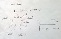
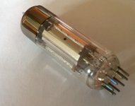
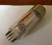
Thanks for your efforts. Despite for me it is not sure if it is a EL84 because the measured heater current is 630mA @ 6,3V and the shape, structure and colour of the anode (s) is significantly different.
Seems that it has three plates or whatever.
Due to the unusual arrangement of the grid rods, I don't believe that it is any sort of conventional pentode.
Could it be a transmitting tube (double Tetrode)
That's a good possibility. There were several tube types that used a common cathode and G2 and G3 to feed a pair plates. The tube you have is likely European so my pictures of American types probably won't help. Look up type #s 6360 and 6939. I would expect anything intended for power operation to have dark color plated to enhance dissipation though.
Another possibility is a beam deflection tube or a sheet beam tube. These used a common cathode G1 and G2 to feed a set of deflection or steering electrodes to direct the electron stream to one or both plates. These were commonly used for modulation and demodulation functions in everything from TV sets to ham and commercial transceivers.
Common type numbers are 7360, 6AR8 and several others I can't remember.
Thanks a lot for your kind support, it has been quite inspiring for me. Just a few minutes ago I came across the tube 6KM8 which is a diode plus a three plate Tetrode, possibly used in electronical instruments. The pinning looks reasonable to my findings.
What do you think?
What do you think?
It is very likely that you have identified the mystery valve as its' appearance is unlike any of the (audio) triode pentode combinations, such as the 6BM8 or 6GW8 series.
What do you think?
That's a good possibility. I remember pulling some of those out of an old organ a long time ago. I'm sure that the tubes are long gone since i got rid of thousands of unneeded tubes when I had to move everything 1200 miles.
But the 6KM8 appears to be not as tall as your baby??
An externally hosted image should be here but it was not working when we last tested it.
+1looks like a thyratron, EL84 seems unlikely because the anodes aren't greyish in colour.
some gas filled.
if you have hv flyback, touch it with one pin, if there is bright plasma to your fingers holding the glass.
somehow getter reminds of cccp tubes.
It's a long shot, to be sure, but . . .
https://rtellason.com/tubedata/6KM8.PDF
page 5 has intriguing curves with the tube connected as a triode. The three plates together have the potential to dissipate 1 watt apiece. (The one notation that challenges me is that the grid 1 needs to be "bypassed" with a 2.2 megohm resistor. I think that means a grid stopper, but I dunno . . .).
Any chance this can be used for the output tube in a bedroom flea-powered guitar amp?
Thanks in advance for any advice or assistance.
Hi,
may be an ECLL800, here:
https://frank.pocnet.net/sheets/062/e/ECLL800.pdf
edit:a picture of the ECLL800
https://cdn-reichelt.de/bilder/web/xxl_ws/A300/ECLL800.png
73
Wolfgang
may be an ECLL800, here:
https://frank.pocnet.net/sheets/062/e/ECLL800.pdf
edit:a picture of the ECLL800
https://cdn-reichelt.de/bilder/web/xxl_ws/A300/ECLL800.png
73
Wolfgang
Last edited:
- Home
- Amplifiers
- Tubes / Valves
- Unknown tube please help.