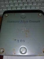
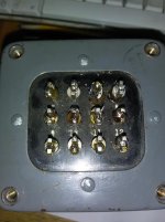
Ohmmeter.
The hundreds-Volt windings will be hundred Ohms. The 117V winding perhaps a dozen ohms. 6V winding sub-ohm.
Once you have that sorted, get a 12V filament transformer and drive the 117V winding. Voltmeter. If the HV winding reads 44V, then it is a 440V winding.
The hundreds-Volt windings will be hundred Ohms. The 117V winding perhaps a dozen ohms. 6V winding sub-ohm.
Once you have that sorted, get a 12V filament transformer and drive the 117V winding. Voltmeter. If the HV winding reads 44V, then it is a 440V winding.
I remember testing transformers salvaged from discarded TV's, radios and HiFi sets as a kid with my trusty Lionel train transformer. It was like a 0 to 18 volt Variac that was isolated from the line. That poor transformer went through many years of abuse and never failed me. I got a giant selenium rectifier stack from an old car battery charger and a DIY "farad bomb" (shoe box full of paralleled caps, probably less than 500 uF) for powering DC things like car radios.
I would feed about 6 volts AC into every pair of wires with the same colors, and measure all the other pairs. Back then almost every transformer used the same common color codes for the wires.
Some TV's had as many as 4 separate heater windings. I could often use them as OPT's in guitar amps. Use the HV with CT winding for the push pull plates and wire all the heater windings in series for the speakers. Pick and choose the combination that sounded the best, or was the loudest.....Hey, I was a pre-teen kid, louder is better, right?
you were experimenting and learning. experimenting and learning is what's better, right?
This was the early 60's and learning was a bit harder than today since information was limited to a few electronics magazines, the library, and bugging the two ham radio operators that I knew, one of which turned out to be wrong more than right. On the positive side, dead TV's, radios, and occasionally a HiFi set or a console organ were rather easy to find. Parts were essentially free.
The definition of "what's better" changed as I learned. At first it was anything that didn't blow up, followed by anything that made sound......
I think designing and building amps is a journey rather than a destination. The journey is where all the fun is.
kuroguy,
Agreed. The journey.
And part of the journey is listening to the amplifiers.
Those who only want to build, and do not want to listen, can offer to send the amplifiers to those of us who enjoy the listening part of the journey.
Agreed. The journey.
And part of the journey is listening to the amplifiers.
Those who only want to build, and do not want to listen, can offer to send the amplifiers to those of us who enjoy the listening part of the journey.
Buzz it out as PRR sais with your DMM, EG 1-4 120 ohms, 2-3 0.6r, 5-6 56r etc, then power it up via a variac & lamp limiter or just the latter to the winding which you suspect is the primary. If the lamp lights up your wrong or the tfmr is toast,keep your hand on the off SW. If the lamp says off connect your DMM and note down all the voltages, EG 1-4 primary, 2-3 7v, 5-6 55v
Andy.
Andy.
Sorry for the late reply. 6 colored wires are easy to figure but 12 terminal are a lot harder. Yours advices will help but how to find the amperage of the secondary winding after finding the voltages.
Regards.
Regards.
Load the secondary and keep an eye on the transformer temperature. See how hot it gets after an hour.
Say your resistance reading of one secondary winding gives you 0.6r, that indicates a low voltage and maybe high current winding. Measure the voltage, say it's 10v, clip a 10r resistor onto this wndg, measure V again, if it's fallen to 9v (10%) then it's a good bet your winding is rated 9v @1A ish
If you have a high voltage wndg, chances are it's rated for lower current, so for 250 - 350v ish windings 100 - 250mA is usual, using ohms law find a suitable resistor as load,increase load till V drops by 10%.
Your tfmr size will also give you a clue, small tfmr = small current, also listen to the tfmr, if it buzzes (and gets hot quick) your loading it too much.
Andy.
Andy, i try this; 720 volts without load - 10% = 609 volts and i got this with a 3500 ohm resistor between the leads. But the two 30 watts resistors i put in serial to achieve this became hot very quickly so i didn't do this test for very long time.
The results 609 volts divided by 3500 ohm = 152 mA Is that correct?
Thanks and regards.
The results 609 volts divided by 3500 ohm = 152 mA Is that correct?
Thanks and regards.
Last edited:
I make that 174mA not 152mA. So, 609 x 0.174= 105.9W this is why two 30W resistors get hot quick. Each resistor probably needs a heatsink to get rid of the heat. Also 10% of 720v is 72v, therefore 720v - 72v = 648v, I'd say your pushing your tfmr by loading it with 3k5 ohms.
Is the 720v AC or DC? A way to load your tfmr is to not rectify the secondary voltage then connect your load and put the resistor in a tub of water, only do this with AC, never DC AND NEVER MAINS and obviously watch what your doing. It's far better to use a heatsink or a fan to cool resistors for a long term test.
Your type of tfmr is usually rated for pretty low current, IE 60 - 100mA, you could try weighing it and multiplying by 0.040 to give you a rough VA rating to confirm/reinforce your test results, see - Getting a VA Rating from a Transformer’s Mass - UK Vintage Radio Repair and Restoration Discussion Forum
Andy.
Well, it was late and i was sleepy.
I redone it.
678vac - 10% = 610vac with a 3775 resistor across the high voltage leads. So 610/3775 = 161 Ma
By chance i had plenty of these 30 watts variable resistors.
I have an other transformer i tested and will be more suitable for my current project.
Best regards.
I redone it.
678vac - 10% = 610vac with a 3775 resistor across the high voltage leads. So 610/3775 = 161 Ma
By chance i had plenty of these 30 watts variable resistors.
I have an other transformer i tested and will be more suitable for my current project.
Best regards.
Sadly my FREED is 657 volts and only 65 Ma, strangely it include a 6v tap and also a 5V tap but a low amperage HV one.
Last edited:
Easily done, I do 3 daft things before breakfast. With electrickery, especially high voltage stuff it's a good idea not to muck about with it if your tired.Well, it was late and i was sleepy.
Thought it might be the case, most tfmr I've come across with more than 400v secondaries are low current. It was probably designed for use in some obscure bit of test gear.Sadly my FREED is 657 volts and only 65 Ma
Andy.
check this article:
page 73
How to Make Power Transformer Substitutions
https://worldradiohistory.com/Archive-Poptronics/50s/59/Pop-1959-04.pdf
page 73
How to Make Power Transformer Substitutions
https://worldradiohistory.com/Archive-Poptronics/50s/59/Pop-1959-04.pdf
- Home
- Amplifiers
- Tubes / Valves
- Unknown FREED power transformer

