Peter, I see that the transformer has 230 VAC in. You have very short creepage distances. I can't see any 8 mm between ground and the mains.
Search the Forum Peranders, we've already discussed that issue, besides, it's wired for 115V.
PS: I'm really dissapointed with your input here. Since it's proto board, you can clearly see that the distance is no less than the pin spread on IEC inlet.
PS: I'm really dissapointed with your input here. Since it's proto board, you can clearly see that the distance is no less than the pin spread on IEC inlet.
Last edited:
Member
Joined 2002
Nice work on the chassis, good idea Peter, Question, does the transformer being in the same case cause any mechanical hum OR interference being that it is close to the psu board and enclosed in the same chassis as the psu board ?
Peter,
I recently got a bunch of these from you.. Are they usable with my B1 buffer build? which section from the 3 section board do I use?
-joe
I recently got a bunch of these from you.. Are they usable with my B1 buffer build? which section from the 3 section board do I use?
-joe
Hi Peter,
Just another quick question about the 120R for the power supply example, is there any wattage requirement?
-joe
Just another quick question about the 120R for the power supply example, is there any wattage requirement?
-joe
Yes, they will work fine with B1 buffer. If you are using original buffer schematic, then only positive supply section is needed. It would look similar to this, although you might use a different regulator type as well: http://www.diyaudio.com/forums/audio-sector/149672-universal-power-supply-pcb.html#post1907541
I see R9-R10 listed on the F5 amp BOM Excel spreadsheet...a 3W 2.2K. I presume this is a bleeder resistor that goes somewhere on the PSU board? I also presume that you would need a total of 4 for a symmetrical supply?
EDIT: I guess the BOM I am referencing is more of a "generic" PSU BOM and not for Peter's PSU board. That being said, is there a spot for a bleeder resistor on the universal PSU board? Is it absolutely necessary?
EDIT: I guess the BOM I am referencing is more of a "generic" PSU BOM and not for Peter's PSU board. That being said, is there a spot for a bleeder resistor on the universal PSU board? Is it absolutely necessary?
Last edited:
I never used those bleeder resistors in my amps. If you need one, you can attach it directly to cap pins from the bottom.
Got it...I was looking at the spreadsheet you had referenced in one of the F5 threads...
Funny...I don't even have my aleph mini done yet and I am already ordering parts and planning the F5...
Funny...I don't even have my aleph mini done yet and I am already ordering parts and planning the F5...
What is the optimal grounding scheme for this PSU when used as V+/V- ? It is for an F5 amp.
Specificaly where is the best place to pick up the chassis ground? Best place to hook up the neg speaker terminals? Do the two center "ground" traces need to be jumpered together?
Thanks!
carl
Specificaly where is the best place to pick up the chassis ground? Best place to hook up the neg speaker terminals? Do the two center "ground" traces need to be jumpered together?
Thanks!
carl
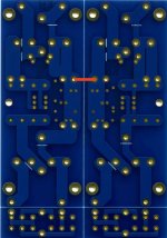
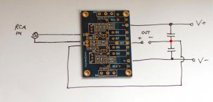
Yes, it's recommended to connect center ground traces (red jumper in attached pic). That would be your power star ground where all other grounds are connected (also the chassis ground). Attached is also wiring diagram for F5 amp.
Attachments
Last edited:
Thanks Peter,
I essentially connected as you suggest with the exception of not using the jumper on the PSU board. I ran 6 independent ground leads from the GND of the PSU - one to each neg speaker terminal, one to each amp board, and two to the chassis(one from each side).
Everything appears to be functioning normally and the amp is quiet.
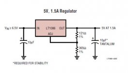
Now, for those who were wondering what are all those additional components for, here's the picture of the regulator circuit with LT1086. Of course this is no good for power amps, but works fine with preamps, active filters etc.
What kind of parts did you use in the regulator? I can only see the Nichicon (what value?) and the LT part...
Just follow the datasheet: http://www.linear.com/pc/downloadDocument.do?navId=H0,C1,C1003,C1040,C1055,P1358,D1722
The large caps in a pic are 4,700uF
The large caps in a pic are 4,700uF
Attachments
The rectifier section accepts high power diodes mounted as in a picture below (they can be attached directly to a chassis for heat dissipation, isolation pads needed). The board is designed mainly for 3 pin rectifiers, but will work with other diodes packages as well. Here's MUR3060:
I may have made an error here, you say isolation pads are needed? Nuts I used transistor grease and put them directly to the case. I guess I need to remove the grease and use isolation pads here then? I havent fire it up yet thank goodness!
Russellc
Last edited:
Depends on the rectifiers you use. The ones I use FOR MY F5 HERE do not need to be isolated.
I did not deploy the use of Peter's rectifier boards though. The Vishay rectifiers are cheaper and a little easier to use.
I did not deploy the use of Peter's rectifier boards though. The Vishay rectifiers are cheaper and a little easier to use.
Depends on the rectifiers you use. The ones I use FOR MY F5 HERE do not need to be isolated.
I did not deploy the use of Peter's rectifier boards though. The Vishay rectifiers are cheaper and a little easier to use.
I uised the MUR 3060 and Peters boards
russellc
A-ha - yes you will need silpads or something. I started down that path and thought I would try the vishay units out to save some $$$ and they work fine.
- Home
- More Vendors...
- Audio Sector
- Universal Power Supply PCB