Pass DIY Addict
Joined 2000
Paid Member
My vote is for putting it in your PSU chassis. Keeps magnetic fields from the coils out of your amp. Also allows a somewhat more flexible layout with your amp chassis.

You could rather say: "Only 10 amperes of steady current."Only 1volt of maximum continuous working voltage!
Do your plans require more than that? Taking a class B 8 ohm totem pole as 50 ohm equivalent, maybe 35 ohms in class A, so stereo 4 Ohms A is like 9 Ohms. 10 Amps implies 90 Volt (+/-45V) supply. This is like 250 Watts per channel. There are many such amps but they rarely run frills like C-r-C filtering.
where is more convenient, especially if you want to use one PSU to combine with various amps
PSU case
PSU case
Powercon also, just check DC capability in datasheet
Though, if PL use them for XS amps, why not
Though, if PL use them for XS amps, why not
I would suggest the full CLC in the PSU chassis, and a third bank of C in the amplifier chassis.
😉
😉
Pass DIY Addict
Joined 2000
Paid Member
^^^^
This will get you close to a CLCRC with your power umbilical acting as a small resistance before the final banks of caps.
This will get you close to a CLCRC with your power umbilical acting as a small resistance before the final banks of caps.
...and tucking that final C nice and close to the power MOSFET's that are drawing the current would be fantastic. I kinda wish these kit pcb's on offer had this option built in to make this easy peasy. And speaking of caps, ESR and ESL can be significantly lowered by using several smaller caps in parallel instead of a single big one. Big reservoir caps aren't great at high frequencies. Bypassing with a quality 1uF film cap can help. A .1uF / 1 ohm zobel, and a low ESR / ESL 100uF electrolytic cap also in parallel helps take care of the resonance and impedance peaks with this type of arrangement.
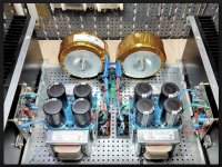
I will soon be building a dual mono outboard power supply for playing with different amps.
Current plan is to shaping up to look a lot like @peppennino ’s Aleph J PSU build (his pic attached) I’ll be using ZM’s cap bank and NTC boards.
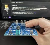
I have a few greenhorn questions regarding the cap bank board:
Current plan is to shaping up to look a lot like @peppennino ’s Aleph J PSU build (his pic attached) I’ll be using ZM’s cap bank and NTC boards.
I have a few greenhorn questions regarding the cap bank board:
- What value/wattage should be used for the LED resistor?
- What kind of LED is recommended?
- Is the little NTC between the chassis connection and output GND optional, but recommended?
Attachments
1. 1K per rail volt; standard 0207 MF adequate; so 20K-27K, whatever you have in drawer
2. any, except those declared for automotive ( direct 12Vdc connection)
3. must have; 10mm Dia, 10-15R
2. any, except those declared for automotive ( direct 12Vdc connection)
3. must have; 10mm Dia, 10-15R
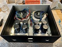

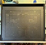
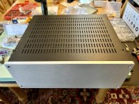
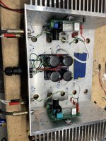
My M2 was humming in both of these chassis. One has the SLB power supply, one had my V8 CRCRC power supply. Both of these are chassis from Tim Rawson amps, and they both look like swiss cheese because they have housed multiple circuits: Aleph 5, F2, F3, F5, F7, AJ, J2.... I had trouble with HUM, and I think the small internal dimensions of the case with the donut right next to amp boards was the cause.
This thread inspired me to try an external case. A year ago I made some little cap bank PCB's for the amp chassis. I finally got a little time to implement this concept.
I chose to use the chassis with SLB as the power supply in one box, and M2 (Prasi boards) + a 22kuF per rail per channel cap banks in the other box.
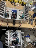
The umbilical is Positive (Red), Negative (Black), Audio Ground (Green), & Chassis Ground (Green/Yellow).
The cable runs through a cable gland on the PSU side (DK p/n 137-CGM16N35-ND)
The cable is in a piece of spare techflex.
The umbilical connector is a female Hirschmann p/n CA 3 LD
The amp chassis connector is a Hirschmann p/n CA 3 GS
Connectors are rated for 10A DC / 16A AC
Grounding scheme
IEC ties to chassis.
SLB goes to Chassis through a NTC.
The umbilical Green/Yellow ties to chassis on both sides.
Audio Ground floats (with respect to chassis ground) in the amp chassis, it's tied back to the Audio Ground on the SLB.
The hum is gone, and the amp is dead quiet. And I can now say I've used/upcycled this Rawson chassis for yet another purpose.
This thread inspired me to try an external case. A year ago I made some little cap bank PCB's for the amp chassis. I finally got a little time to implement this concept.
I chose to use the chassis with SLB as the power supply in one box, and M2 (Prasi boards) + a 22kuF per rail per channel cap banks in the other box.
The umbilical is Positive (Red), Negative (Black), Audio Ground (Green), & Chassis Ground (Green/Yellow).
The cable runs through a cable gland on the PSU side (DK p/n 137-CGM16N35-ND)
The cable is in a piece of spare techflex.
The umbilical connector is a female Hirschmann p/n CA 3 LD
The amp chassis connector is a Hirschmann p/n CA 3 GS
Connectors are rated for 10A DC / 16A AC
Grounding scheme
IEC ties to chassis.
SLB goes to Chassis through a NTC.
The umbilical Green/Yellow ties to chassis on both sides.
Audio Ground floats (with respect to chassis ground) in the amp chassis, it's tied back to the Audio Ground on the SLB.
The hum is gone, and the amp is dead quiet. And I can now say I've used/upcycled this Rawson chassis for yet another purpose.
Attachments
Nice work, rhthatcher! Rawson rescue satisfaction yet again! I’m hoping to end up with silent power delivery, as well.
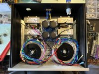
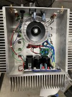
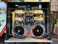
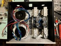
Space is tight in my little 3U Galaxy! Before I make final placements, I wanted to throw this dual mono plan (attached image) by the forum. I’m using ZM’s cap bank boards and NTC boards (blue rectangles). The NTC boards will attach to the side panels. The cap banks are stacked. The toroids are AS-3218. There will be safety earth from the IEC inlet to the chassis. The DC output will go through Neutrik power-con terminals. My questions:
Space is tight in my little 3U Galaxy! Before I make final placements, I wanted to throw this dual mono plan (attached image) by the forum. I’m using ZM’s cap bank boards and NTC boards (blue rectangles). The NTC boards will attach to the side panels. The cap banks are stacked. The toroids are AS-3218. There will be safety earth from the IEC inlet to the chassis. The DC output will go through Neutrik power-con terminals. My questions:
- Are there any issues with stacking 2 monolithic bridges on top of each other with a spacer?
- Is splitting the AC mains at the IEC inlet and routing around the perimeter asking for trouble (should the AC mains go toward the front toroids first and then split to the NTC boards)?
- Will I need a separate safety earth connection between power supply chassis and amp chassis?
Attachments
Last edited:
Von Ah - that's going to be hefty!
Here are some thoughts
1. You want the bridges on the floor or walls so they are heatsinked. Can you move the donuts to the far corners nearly touching the walls/face (leave a little gap) which could allow room to run 4 bridges next to each other between the donuts. Could you make that fit? It will be tight, but is a possibility. Move the cap bank boards further back if you need that space. Again, It will be tight.
2. Consider IEC/Switch to 1 fuse per channel (drill holes for 2 separate fuse holders near IEC), then run mains to each NTC board. So the only shared wiring is at the IEC, and after that you're 100% dual mono including fuses. Make sense?
3. If you're running 2 cables, I think you'll want an earth cable on each umbilical.
Do ZM's cap bank boards have NTC to chassis/earth ground? Can't forget that connection.
Good points, thank you!
I will try move the cap boards back further for bridge room. I‘ll try to move the donuts a bit toward the corners, too (less confident in that working). Understood on the IEC plus fuses. ZM’s cap boards do have such a connection. For the umbilical, should I get 4-terminal PowerCon connectors, then?
I think I’ll be drilling a lot more holes in the baseplate and bottom panel. Too limited, otherwise. For the sake of covering different options, would it be frowned upon to have the bridges on the walls (longer cables)?
Last edited:
If maximum separation between AC and DC is desired, locate both transformers on one side of the case, locate the AC inlet at the same side of the case close to the side wall and run the AC lines against the side, locate the DC outputs on the other side of the case close to the side wall, and locate power supply filtering on that side of the case. Left/right symmetry is not always the best for best performance.
However you have your back panel already prepared with cutouts.
With your current arrangement probably the thing to do is to run the AC wires down the centreline under the bottom plate.
However you have your back panel already prepared with cutouts.
With your current arrangement probably the thing to do is to run the AC wires down the centreline under the bottom plate.
That’s a good alternative, Ben. Thanks. I’ll continue shuffling things around. It wouldn’t be the end of the world to order another back panel.
- Home
- Amplifiers
- Pass Labs
- Universal Outboard Power Chassis for Pass