Hello.
I want to get headphones for mixing and I have settled on the Sennheiser HD600. This set features a standard (for pro cans) 300ohm input impedance.
This is all nice and dandy, however, the headphone jack on my audio interface, a Roland Quad Capture, has an output impedance of 47ohm. A value which those of you who are aware of the technicalities, would be quick to notice is much too high to drive the Sennheiser properly and would result in unpredictable performance, boomy bass, distortion, etc.
The recommended output impedance for the Sennheiser HD600 is as low as you can get. 0 ohm if possible.
Practically, I could get a ~2ohm headphone amp for $100-$200 and get done with it, but I'm not willing to shell out this kind of money–quite near how much I spent on the interface itself.
After some research, I discovered unity gain buffers and how they can be used to lower the output impedance of a source–which on first sight sounds like a gift–exactly what I need to achieve my goal.
However from what I understand, unity gain buffers are not some plug-n-play component you can get off the shelf, but a circuit you have to design (and then assemble of course, which is the easier part).
I also understand it is quite a simple circuit so I feel this project is something I can accomplish. But I'm getting ahead of myself. Here are a few questions:
I think by getting answers to these unknowns from experienced folk like you guys, I can make a smarter decision. Thanks!
I want to get headphones for mixing and I have settled on the Sennheiser HD600. This set features a standard (for pro cans) 300ohm input impedance.
This is all nice and dandy, however, the headphone jack on my audio interface, a Roland Quad Capture, has an output impedance of 47ohm. A value which those of you who are aware of the technicalities, would be quick to notice is much too high to drive the Sennheiser properly and would result in unpredictable performance, boomy bass, distortion, etc.
The recommended output impedance for the Sennheiser HD600 is as low as you can get. 0 ohm if possible.
Practically, I could get a ~2ohm headphone amp for $100-$200 and get done with it, but I'm not willing to shell out this kind of money–quite near how much I spent on the interface itself.
After some research, I discovered unity gain buffers and how they can be used to lower the output impedance of a source–which on first sight sounds like a gift–exactly what I need to achieve my goal.
However from what I understand, unity gain buffers are not some plug-n-play component you can get off the shelf, but a circuit you have to design (and then assemble of course, which is the easier part).
I also understand it is quite a simple circuit so I feel this project is something I can accomplish. But I'm getting ahead of myself. Here are a few questions:
- Am I correct in my understanding that a unity gain buffer could solve my problem?
- Am I correct in my assumption that a unity gain buffer is something that would cost a few $ to assemble?
- Am I correct in my assumption that unity gain buffers, being a very simple component, do not alter the signal (ie. frequency response)? - again this is important to me as I'll be using it for mixing.
I think by getting answers to these unknowns from experienced folk like you guys, I can make a smarter decision. Thanks!
Last edited:
A unit gain buffer consisting of a couple of opamps would drive 300 ohms and have an output impedance close to zero over the audio band. All circuitry has limitations on frequency response but suitable opamps would easily extend way over the audio band and also go down to DC (if you wanted that). Cost for parts for a buffer could be around $10-15, say two opamps and a decent volume control. Then you need sockets for input and output.
You also need a power supply which could even be battery for this. Or there is discrete using separate transistors. That could be very simple too.
Its one thing coming up with a simple and suitable audio circuit... the harder part is designing it properly so that there are no switch on/off thumps and noises etc. All doable but it adds to the complexity and cost a little.
In many ways the most important question is how will it be powered ? Mains or battery.
Thank you very much. Definitely sounds like a direction worth taking.
What would be the voltage requirement of such a circuit? Then I would be able to answer your question.
What would be the voltage requirement of such a circuit? Then I would be able to answer your question.
Thanks, though a little bit of background would definitely help. 🙂
BUF634 is a driver chip from Texas Instruments, it's sound is preferred over the LME49600 (also from TI). I don't think you could do better than Patrick's suggestion for only $25.
BUF634 is a driver chip from Texas Instruments, it's sound is preferred over the LME49600 (also from TI). I don't think you could do better than Patrick's suggestion for only $25.
Cheers. Although I couldn't find any technical information about this module. How do I use it? From what I understand, I am going to plug the buffer into the headphones jack on my audio interface, and then plug the headphones into the buffer (or am I wrong?). Soldering the connectors is not a big deal, but where to? This module seems to have only 3 contacts? And where does the power voltage go into?
Also, why exactly is the BUF634's sound preferred over that of the LME49600? Please remember, this setup will be used for mixing, therefore a clinical and flat sound is what I'm after.
Finally, the BUF634 datasheet showcases quite a set of frequency response graphs, but they are all in the Mhz to Ghz range. What should I make out of that?
Thanks.
Thank you very much. Definitely sounds like a direction worth taking.
What would be the voltage requirement of such a circuit? Then I would be able to answer your question.
You've had some good suggestions already. For battery operation we are probably looking at two 9 volts packs as a minimum. That would allow a decent voltage swing to be available for the headphones.
Have you ever looked at the 02 amplifier ?
http://www.diyaudio.com/forums/headphone-systems/193977-objective2-o2-headphone-amp-diy-project.html
For an opamp buffer all you really need is the output stage of this... and its just classic opamp text book design. Two dual opamps and a few other resistors and a volume control. It would accept a line level input directly.
Attachments
I don't have line level output from the audio interface. It has balanced stereo out which is used by the monitors, SPDIF out and headphones out.
Mobility is definitely not required, and a power supply is preferred to batteries. If I'm getting you, I'd need an 18V power supply for this? Quite a hunger this guy has!
Mobility is definitely not required, and a power supply is preferred to batteries. If I'm getting you, I'd need an 18V power supply for this? Quite a hunger this guy has!
Its your headphones that have hunger 😉 being high impedance models they need a relatively high voltage to drive them.
Although it is all a very straightforward project, how you approach it would depend on your construction abilities.
So you need,
1/ A mains PSU. That's easily catered for via countless offerings. Something like a 12-012 or 15-0-15 volt supply would be appropriate.
2/ Determine what the input/s are going to be. If it is balanced then you need appropriate circuitry to deal with that. Scroll down the page for more circuit details.
Balanced Interfaces
I think you could just try driving the headphones from the Roland as is, and it would sound fine. The 47 ohm output impedance is likely a resistor to prevent overload in case of a short. I doubt the 300 ohm impedance of the Sennheiser phones will overload the Roland's output. Just my 2 cents; YMMV.
I think you could just try driving the headphones from the Roland as is, and it would sound fine. The 47 ohm output impedance is likely a resistor to prevent overload in case of a short. I doubt the 300 ohm impedance of the Sennheiser phones will overload the Roland's output. Just my 2 cents; YMMV.
Thanks for chiming in dotneck335. The point is not about overloading the audio interface, I doubt that would happen. I'm wary of the negative effect on the sound quality and frequency response that result of the lower impedance ratio. As described by a user on the Steve Hoffman forums who had already attempted this combination.
2/ Determine what the input/s are going to be. If it is balanced then you need appropriate circuitry to deal with that. Scroll down the page for more circuit details.
The Quad Capture's headphones out is unbalanced and I'm not yet willing to shell at least another $100 to get a balanced link to the headphones, so I'll be keeping it as it is. Unbalanced it is then. 🙂
If you are home constructing then a balanced to unbalanced circuit costs very little to make. A couple of opamps, that's all. I notice Rod Elliots site that I linked to above is currently unavailable. It was OK yesterday.
If you just want unbalanced circuitry all the way through then its really a case of a power supply and an opamp buffer such as the I posted above.
If you just want unbalanced circuitry all the way through then its really a case of a power supply and an opamp buffer such as the I posted above.
True, but the cheapest balanced cable for the Sennheiser HD600 I could find costs as little as $80 and I'm not sure it's worth it.
So just the output stage of the O2 should be sufficient. I had a hunch getting that 0ohm output shouldn't be a complicated endeavor 🙂
So just the output stage of the O2 should be sufficient. I had a hunch getting that 0ohm output shouldn't be a complicated endeavor 🙂
Getting near zero ohms output impedance comes as standard with opamp circuitry.
Seems we were talking about different things here. I was thinking you meant the amp had to have balanced inputs (maybe you meant that as well) but I see you are referring to balanced outputs as well.
Only you can make the decision as to whether going balanced for the outputs is worth it or not.
Seems we were talking about different things here. I was thinking you meant the amp had to have balanced inputs (maybe you meant that as well) but I see you are referring to balanced outputs as well.
Only you can make the decision as to whether going balanced for the outputs is worth it or not.
Sorry, there has definitely been a misunderstanding here 🙂
My signal chain would be as follows:
Roland Quad Capture 47ohm unbalanced headphones out -> unity gain buffer -> 300ohm unbalanced headphones input
My signal chain would be as follows:
Roland Quad Capture 47ohm unbalanced headphones out -> unity gain buffer -> 300ohm unbalanced headphones input
Last edited:
No problem 🙂
So you really just need something like the opamp buffer I posted. Two dual opamps, 2 caps and 6 resistors. You could easily build that and test it using batteries to see what you thought of it.
(Have you actually looked at the headphone output you already have. It may well be possible to reduce the output impedance simply by a resistor change)
I prefer to avoid modifying anything inside the audio interface. It's brand new so I still have the warranty, plus, too risky for a newbie like me 🙂
Actually, I'm thinking of going with the pre-made module Patrick posted yesterday. It just looks like less of a hassle to deal with.
A couple of questions remain unanswered:
Is this transformer enough for a power supply? Or does it require something more complex? Does it need DC or AC power? I Couldn't find detailed specs of the module anywhere. It does say on the eBay page that it outputs 250mA.
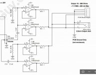
After several inspections I finally realized the 4 golden elements at the bottom end of the PCB are SMP connectors, so I now understand where the signal goes in and where it comes out (newbie, have I already said?)
I'm attaching two pictures of the BUF634 module to resolve another unknown. My intuition tells me the circled areas are points where I can solder my own L+R inputs and outputs:

But if you'll notice the square and circle pads are inverted on the right input:

What do I make out of that?
And the last question is since I'll be wiring an unbalanced stereo output to an unbalanced stereo input, what do I do with the GNDs? Simply split the output ground into the two inputs of the BUF634 module, and reverse it between the module's outputs and the headphones jack? All these questions probably go to show the lack of understanding of the fundamentals of electronics engineering on my side, but as I said, I'm a newbie 🙂
Actually, I'm thinking of going with the pre-made module Patrick posted yesterday. It just looks like less of a hassle to deal with.
A couple of questions remain unanswered:
Is this transformer enough for a power supply? Or does it require something more complex? Does it need DC or AC power? I Couldn't find detailed specs of the module anywhere. It does say on the eBay page that it outputs 250mA.
After several inspections I finally realized the 4 golden elements at the bottom end of the PCB are SMP connectors, so I now understand where the signal goes in and where it comes out
(newbie, have I already said?)I'm attaching two pictures of the BUF634 module to resolve another unknown. My intuition tells me the circled areas are points where I can solder my own L+R inputs and outputs:
But if you'll notice the square and circle pads are inverted on the right input:
What do I make out of that?
And the last question is since I'll be wiring an unbalanced stereo output to an unbalanced stereo input, what do I do with the GNDs? Simply split the output ground into the two inputs of the BUF634 module, and reverse it between the module's outputs and the headphones jack? All these questions probably go to show the lack of understanding of the fundamentals of electronics engineering on my side, but as I said, I'm a newbie 🙂
Last edited:
The transformer produces AC voltage and the module needs DC. So you need a power supply board of some kind containing a rectifier, reservoir capacitors and then voltage regulators.
A 15-0-15 vac transformer produces around 22-0-22 volts DC after rectifying.
I'm sure small complete PSU's are available. You would need to know the recommended voltage for the module. I'm assuming it would 12-0-12 to perhaps 15-0-15 volts DC but you would need to check.
I don't know why the pads are as they are on the board. It might be just to do with the board layout of the copper traces. It would become more obvious when you actually examine one I think.
The single ground from the headphone output would be split and form the two input grounds that the module sees. That's no problem.
Just for ideas, something like this plus the transformer:
VELLEMAN KIT - K8042 - ELECTRONICS KIT, SYMMETRIC 1A PSU | CPC UK
VELLEMAN KIT - K8042 - ELECTRONICS KIT, SYMMETRIC 1A PSU | CPC UK
- Status
- Not open for further replies.
- Home
- Amplifiers
- Headphone Systems
- Unity gain buffer for Sennheiser HD600