Hi I am in need of some help repairing a unison s8. The symptom is the front end valves, 3 of, do not light. The output valves do light. I could use a circuit diagram but unison won't supply one, henley services the company that supply's and provides repair work on them do not appear to help and just won't me to send it to them. My friend who owns the amp is against this as the amp is over 20 years old and he afraid it might get damaged in the post. He is also afraid it it might be more expensive then he can afford. Iam sure with a circuit diagram I can fix it. Can anyone help. Many thanks Cliff.
The smart thing to do is to trace the heater circuits from the transformer to the tube pins. Somewhere along the way you will find a broken wire.
Since it effects 3 tubes the fault should lie before the wiring separates to each of the three tubes. The heater pins of the tubes are normally obvious from the thick wiring but the data sheet will tell all.
A simple DMM would be helpful.
Jan
Since it effects 3 tubes the fault should lie before the wiring separates to each of the three tubes. The heater pins of the tubes are normally obvious from the thick wiring but the data sheet will tell all.
A simple DMM would be helpful.
Jan
Thanks Jan its not that simple, the heaters are in series and the supply chain is conveluted to put it mildly. No 6.3v tx on this front end. O for a look at the circuit.
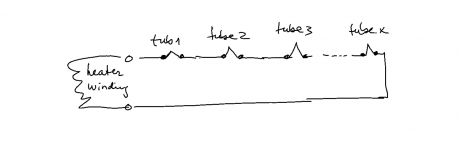
When it is in series it is even easier. Just measure the voltage along the chain, from the transformer to the 1st tube, then after the 1st tube, then to the 2nd tube, then after the 2nd tube, and so on.
All you need to do is follow the wiring.
Or even more simple: measure the heater voltage across each tube. The open one will have all the voltage across it.
Jan
All you need to do is follow the wiring.
Or even more simple: measure the heater voltage across each tube. The open one will have all the voltage across it.
Jan

Hi Jan l have been repairing valve amps for years and now how simple an O/C heater chain should be to repair. However this one is like nothing lve seen before. The chain starts from a full wave rectifier block and has 75v out put, each valve has a zenner across its heaters and the chain is continuous to an ouput plug which then heads off to go to another power supply, which appears to have nothing to do with the heaters. I cannot find any return to the other end of the full wave block. All components in the circuit check OK and there are no bad joints or oc wire connections l can find, all voltages appear to be present and that includes the 750v for O/P valves. Of course being double sided print it makes circuit trace a bit more difficult. I keep thinking lve missed something obvious, but l'am the second engineer to look at this as the first one gave up. Many thanks Cliff.When it is in series it is even easier. Just measure the voltage along the chain, from the transformer to the 1st tube, then after the 1st tube, then to the 2nd tube, then after the 2nd tube, and so on.
All you need to do is follow the wiring.
Or even more simple: measure the heater voltage across each tube. The open one will have all the voltage across it.
Jan
But if you measure across all heaters (I mean between the two heater pins on the tube base, NOT to ground), you should find one that's off, otherwise all would be OK.
Jan
Jan
Hi Jan, not quite sure what you mean. I have wth my multi meter check from one valve to the next and all are connected, if l do an ohms reading from top to bottom of the chain wth the valves in place l get an ohms reading of 48 ohms showing me that all is continues. What would reading the voltage across each valve tell me, if there was an O/C in the chain the ohms reading would shown that. I am going away for 10days tomorrow so the amp will now have to wait till l return. I really appreciate your help in this matter and wish to carry on with the investigation when l get back. I will have access to the Internet while away but not the amp. I hope we can continue this on my return so thank you for your help to date. Cliff.
You have a bunch of tubes with the heaters in series, right, and some (all) of the heaters do not glow.
Measuring between the two heater pins on each tube will tell you which one is open, because all of the heater voltage will show on that tube, while the voltage between the heater pins of the good tubes will read zero (because there is no current flow).
The other thing is that maybe the whole heater supply is gone. In that case you measure zero volts between the very first heater pin in the series and the very last one. If you have problems finding the start and end of the heater string, pick a heater pin and trace in both direction until you find the heater source.
Jan
Hi Jan,the valves have been replaced to no avail. The problem as l see it is there's no complete circuit as there is no current flowing. But l cannot find how the circuit from the end of the heater chain returns to the negative end of the rectifiers. A circuit would be a great help. Many thanks Cliff.
All the heater pins are known from the tube data sheet. It's really a no-brainer to follow the chain and find where the heater is open (that one has all the voltage)...
... or find the way back to the heater supply to check if the transformer is defect. No need for any schematics.
Jan
... or find the way back to the heater supply to check if the transformer is defect. No need for any schematics.
Jan
Attachments
Hello. I also encountered the problem that the three signal tubes at the front of my s8 are not bright. Later, I checked that there was a problem with the central high-voltage board. You can check this part, and I hope this will help you. Good luck.
- 非常感謝您的幫助。我只需要這個示意圖。但是我的DRIVER板上的幾個電阻都燒壞了。我好苦惱。因為我不知道那是一種什麼樣的反抗。
Mod edit:
Thank you very much for your help. I just need this schematic. But several resistors on my DRIVER board burned out. I'm so distressed. Because I don't know what kind of rebellion that is.
Last edited by a moderator:

@0519
Did the above post appear to you in English in your browser when you posted it? No worries if not... just try to remember to post in English.
Any help with this issue appreciated 🙂
https://www.diyaudio.com/community/...with-translation-software.400362/post-7378738
Last edited:
Unison S8 Bill of material, copied from manufacturer paper :
no liability from my sideRESISTORS
R1 L / R Resistor 10 MOhm 1/2WR2 L / R Resistor 150 kOhm 1W
R3 L / R Resistor 10 MOhm 1/2W
R4 L / R Resistor 150 kOhm 1W
R5 L / R Resistor 136 Ohm 1/3W 1%
R6 L / R Resistor 150 kOhm // 150 kOhm 1W
R7 L / R Resistor 15 kOhm 1/3W 1%
R8 L / R Resistor 1.8 kOhm 1/3W 1%
R9 L / R Resistor 330 kOhm 1W
R10 L / R Resistor 1 kOhm 1W
R11 L / R Resistor 22 Ohm 5W
R12 L / R Resistor 22 Ohm 5W
R13 L / R Resistor 330 Ohm 10W
R14 Resistor 56 kOhm 3W + 56 kOhm 3W
R15 Resistor 2.2 kOhm 3W
R16* Resistor 46.4 kOhm 1/3W 1%
R17* Resistor 20 kOhm 1/3W 1%
R18 L / R Resistor 0.1 Ohm 5W
R19 Resistor 3.3 Ohm 5W
R20 Resistor 3.3 Ohm 5W
R21 Resistor 3.3 Ohm 5W
R22 Resistor 220 Ohm 7W
R23 Resistor 220 Ohm 7W
R24 Resistor 220 Ohm 7W
R25 Resistor 220 Ohm 7W
R26 Resistor 220 Ohm 7W
R27 Resistor 220 Ohm 7W
R28 Resistor 470 kOhm 3W
R29 Resistor 1M 1/2W
R30 Resistor 1M 1/2W
R31 Resistor 1M 1/2W
R32 Resistor 4.7 Ohm 5W
Rn1 Resistor 330 kOhm 3W
RA Resistor 1MOhm 1/3W 1%
RB Resistor 100kOhm 1/3W 1%
RV Varistor 250V (or 150V)
R16* and R17* F ECC82 Adjustment
CAPACITORS
C1 L / R Capacitor 0.47uF 63VC2 L / R Capacitor 0.22uF 400V
C3 L / R Capacitor 100uF 100V
C4 L / R Capacitor 0.22uF 400V
C6 Capacitor 100uF 400V
C7 Capacitor 1.000uF 63V
C8 Capacitor 100uF 100V
C9 Capacitor 100uF 100V
C10 L / R Capacitor 10.000uF 16V
C11 L / R Capacitor 10.000uF 16V
C12 L / R Capacitor 100uF 400V
C13 Capacitor 220uF 400V
C14 Capacitor 220uF 400V
C15 Capacitor 220uF 400V
C16 Capacitor 1.000uF 400V
C17 Capacitor 1.000uF 400V
C18 Capacitor 1.000uF 400V
C19 Capacitor 1.000uF 400V
C20 Capacitor 1.000uF 400V
C21 Capacitor 1.000uF 400V
C22 Capacitor 470uF 400V
C23 Capacitor 470uF 400V
Cn1 Capacitor 680nF 275Vac
Cn2 Capacitor 680nF 275Vac
Cf L / R Capacitor Feedback Adjustment
Ci L / R Capacitor 47pF 50V
OTHER COMPONENTS
BR1 Bridge Diodes 1.000V 1.5ABR2 Bridge Diodes 600V 4A
BR3 Bridge Diodes 600V 4A
BR4 Bridge Diodes 600V 4A
CK Choke 5H
D1 Diode BY255
D2 Diode BY255
D3 Diode BY255
DS L / R Schottky Diode
DZ1 Zener Diode 14V 5W
DZ2 Zener Diode 14V 5W
DZ3 Zener Diode 14V 5W
DZ4 Zener Diode 200V 5W
DZ5 Zener Diode 200V 5W
F Fuse T500mA 250V
F1 Fuse T1.25A 250V
F2 Fuse F500mA 250V
F3 Fuse F315mA 250V
F4 Fuse T6.3A 250V (V = 100V😉 mains fuse
Fuse T3.15A 250V (V = 230V😉 Mains fuse
P120 + 20 KA Potentiometer
SW1 Input Switch
SW2 Tape Monitor Switch
SW3 Switch
TA Power Supply Transformer
TU L / R Output Transformer
V1 845
V2 845
V3 L ECC 82
V4 R ECC82
V5 L / R ECC82
NTC (mains)
Suppressions parts
NTC (mains)
RV Varistor 250V (or 150V)
Rn1 Resistor 330 KOhm 3W
Cn1 Capacitor 680nF 275Vac
Cn2 Capacitor 680nF 275Vac
- 非常感謝您的幫助。我只需要這個示意圖。但是我的DRIVER板上的幾個電阻都燒壞了。我好苦惱。因為我不知道那是一種什麼樣的反抗。
Mod edit:
Thank you very much for your help. I just need this schematic. But several resistors on my DRIVER board burned out. I'm so distressed. Because I don't know what kind of rebellion that is.
Last edited by a moderator:
Thank you for conveying. i will obey.
@0519
Did the above post appear to you in English in your browser when you posted it? No worries if not... just try to remember to post in English.
Any help with this issue appreciated 🙂
https://www.diyaudio.com/community/...with-translation-software.400362/post-7378738
- Home
- Amplifiers
- Tubes / Valves
- Unison S8