Unique Output Stage With Multiple Drivers
I bought a new amp as a stand in to replace one that I accidentally burned up after a little slip with a test probe. Being the silly objectivist that I am, I basically just went around schematic shopping to get something I figured probably would sound and perform fairly similar and possibly a little better. I found a schematic for an amp that looked promising, and bought its big brother even though I couldn't find the schematic for that amp.
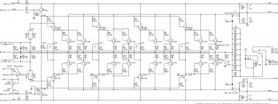
Fast forward, and I managed to find a schematic after a lot of digging. It was not quite what I expected. The input stage and the VAS were similar (but still a little different). Those minor differences were sort of a surprise, but that wasn't the real big surprise. The output stage was. I don't think I've ever seen anything quite like this. Yes, it's a triple darlington (at least I think it still qualifies), but the way they drive the outputs is weird. Instead of a single pair of drivers to drive all eight output pairs, they use a pair of drivers to drive four sets of two pairs of outputs.
Anyone ever seen anything remotely like this? I did a bunch of schematic digging, and I can't find any other amp where something like this has been done. Maybe it will give someone a good idea for a project. Does anyone have any idea why you would do such a thing and whether it would be advantageous?
I bought a new amp as a stand in to replace one that I accidentally burned up after a little slip with a test probe. Being the silly objectivist that I am, I basically just went around schematic shopping to get something I figured probably would sound and perform fairly similar and possibly a little better. I found a schematic for an amp that looked promising, and bought its big brother even though I couldn't find the schematic for that amp.
Fast forward, and I managed to find a schematic after a lot of digging. It was not quite what I expected. The input stage and the VAS were similar (but still a little different). Those minor differences were sort of a surprise, but that wasn't the real big surprise. The output stage was. I don't think I've ever seen anything quite like this. Yes, it's a triple darlington (at least I think it still qualifies), but the way they drive the outputs is weird. Instead of a single pair of drivers to drive all eight output pairs, they use a pair of drivers to drive four sets of two pairs of outputs.
Anyone ever seen anything remotely like this? I did a bunch of schematic digging, and I can't find any other amp where something like this has been done. Maybe it will give someone a good idea for a project. Does anyone have any idea why you would do such a thing and whether it would be advantageous?
Attachments
Last edited:
Looks like an EF3 where the pre-driver is driving paralleled driver / output groupings. Might make for an interesting simulation compared to the traditional EF3 arrangement.
That is output stage of Mackie M2600 professional power amplifier with separately each driver for each output transistor. This style requires all drivers and power transistors should be matched Vbe/Hfe.
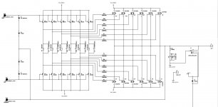
It's also same as MOSFET output stage below, it's come from a hi-end product.
It's also same as MOSFET output stage below, it's come from a hi-end product.
Attachments
Looks like an EF3 where the pre-driver is driving paralleled driver / output groupings. Might make for an interesting simulation compared to the traditional EF3 arrangement.
I think it would be really interesting to model for people who are doing higher powered DIY amps. There aren't many of those, though, so the usefulness of this might be somewhat limited. Almost certainly, it will never be used in a commercial product ever again since high powered commercial amps have all gone the way of rail switchers or all digital.
It would be interesting to see what benefits this yields. There has to be something, or it would not have been done. Another poster was right about who did this design. It is a not a "cost no object" audiophile company. Rather, it was a clean sheet commercial design done in the late nineties. It would not surprise me if it was the last clean sheet high power Class A/AB amp any major non-audiophile (read: engineering-based) company ever did.
The real winner in the series is the mid-power amp, the 1400. Common as hen's teeth, and dirt cheap. A schematic is attached. You won't find a circuit design and a parts list like this is any other amp this cheap on the used market. It doesn't have the unique output stage of the bigger amp, but the other stages are just as nice if not a little nicer. The downside is basically the entire amp (both channels) is on one PCB and lots of surface mount, so buying them to play with is probably a non-starter.
But I'm getting a little off topic.. Back to the output stage. Advantages? Disadvantages?
Attachments

Krell KMA160, KSA250 were built similarly. Each driver feeds just 3 paralleled outputs. I guess it was the best compromise between linearity, current gain, power delivery and Ft for the chosen device (MJE15030/31). Cannot see it as unique or exciting.
I have seen quite a few manufacturers increasing the output capability by adding on driver+output stages.
That's what is in post1. Three additional driver+output stages.
And pay attention to Walkalone
That's what is in post1. Three additional driver+output stages.
And pay attention to Walkalone
requires all drivers and power transistors should be matched Vbe/Hfe.
Modern sustained beta OPS devices and associated drivers make this approach obsolete IMV. Most of these device pairs come matched to within 10 % for hFE as well. Favor in the outstanding SOA capability and you have the best of all worlds if you use an EF3 (aka 'Locanthi') topology.
Like SY said, we are living in the golden age of audio
Like SY said, we are living in the golden age of audio
Modern sustained beta OPS devices and associated drivers make this approach obsolete IMV. Most of these device pairs come matched to within 10 % for hFE as well. Favor in the outstanding SOA capability and you have the best of all worlds if you use an EF3 (aka 'Locanthi') topology.
Like SY said, we are living in the golden age of audio
Very true, but I still think this is a rather nice implementation using easy to get parts. There were a few threads describing approaches like this, but no one ever seemed to have a schematic where it had been done.
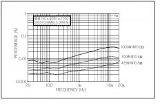
What is really astonishing is the rest of the design, particularly the m1400 schematic I posed. Take a look at it -- I think it's actually somewhat similar to your designs. Then bear in mind most of these things were sold as DJ amps and are $200 used. It has to be one of the most overly engineered DJ amps ever put into production. THD20 never rises above .008% if their Audio Precision measurements are to be believed.
There's a very simple reason for that design: It's widely scalable. Just add more 'Darlingtons' and PS. The BIAS drive doesn't have to be canged (practically only voltage dependent), even the protection works the same (just voltage check (I-SENSE)).
There's a very simple reason for that design: It's widely scalable. Just add more 'Darlingtons' and PS. The BIAS drive doesn't have to be canged (practically only voltage dependent), even the protection works the same (just voltage check (I-SENSE)).
Oddly enough though, it was never scaled. And I'm not sure where you would go with it if you wanted to scale it. Getting past 100VDC for your rails is pushing it pretty hard on a straight class AB design.
Current scaled.
One set for an 8ohms capable power amplifier.
Two sets for a 4ohms capable amplifier.
Four sets for a 2ohms capable amplifier.
One set for an 8ohms capable power amplifier.
Two sets for a 4ohms capable amplifier.
Four sets for a 2ohms capable amplifier.
Current scaled.
One set for an 8ohms capable power amplifier.
Two sets for a 4ohms capable amplifier.
Four sets for a 2ohms capable amplifier.
That's true. You could easily scale this, and it's a good proof of concept at least that this works well since thousands of these amps are in service. What I meant was that it was never actually scaled commercially. This design was a one-off with the lower power amp in the product line having a single driver and four outputs, but the rails were also 20VDC lower.
For reference purposes, the THDvFrequency plot at full power is attached. Of course, it isn't just the output stage responsible for this level of performance at these power levels, but it's still quite impressive.
Attachments
What I meant was that it was never actually scaled commercially. This design was a one-off with the lower power amp in the product line having a single driver and four outputs, but the rails were also 20VDC lower.
That's also a scaling which works better than a lot other amplifier concepts. They were scaled commercially, there were quite some active speakers with such amps. And don't forget: Mass production is a lot cheaper than having multiple versions.
There's also another big advantage: Once you have a source of narrowly toleranced transistors, the production line testing is so much faster and easier. Also repair is done within minutes, no bias or DC adjust. It could even be done on-field, which is remarkable.
Current scaled.
One set for an 8ohms capable power amplifier.
Two sets for a 4ohms capable amplifier.
Four sets for a 2ohms capable amplifier.
Exactly. It's also a very easy way for a smaller manufacturer to get reasonable unit numbers for cheap production and a very low number of different parts you have to keep in stock.
Exactly. It's also a very easy way for a smaller manufacturer to get reasonable unit numbers for cheap production and a very low number of different parts you have to keep in stock.
True, but the usual way of driving multiple output is to use another output as a driver. Much simpler. However, that would mean using a fairly slow MJL21193 as a driver. I assume that must carry a distortion penalty, and that is what they were trying to avoid. Throwing an extra 12 devices into a stereo amplifier and mounting them all on the heatsink is not a very good production efficiency.
Last edited:
True, but the usual way of driving multiple output is to use another output as a driver. Much simpler. However, that would mean using a fairly slow MJL21193 as a driver. I assume that must carry a distortion penalty, and that is what they were trying to avoid. Throwing an extra 12 devices into a stereo amplifier and mounting them all on the heatsink is not a very good production efficiency.
It is much cheaper, you can outsource it, you don't need high qualified personnel for the production yourself, save a lot on adjustment/QC/repair and don't need to buy the machinery for mass production. The extra devices are not going to increase the production costs by much because you are ordering in much higher volumes. That lowers the risk for production and investment to a minimum - excellent solution, unless you already have everything in the company. It's not the fastest way to produce it but that's not always priority.
It is much cheaper, you can outsource it, you don't need high qualified personnel for the production yourself, save a lot on adjustment/QC/repair and don't need to buy the machinery for mass production. The extra devices are not going to increase the production costs by much because you are ordering in much higher volumes. That lowers the risk for production and investment to a minimum - excellent solution, unless you already have everything in the company. It's not the fastest way to produce it but that's not always priority.
You lost me there. At least I think I've figured out to an extent why they did this after digging through other threads.
You lost me there. At least I think I've figured out to an extent why they did this after digging through other threads.
That's pretty easy: You only see the parts. That's simply not correct, the parts are only a fraction of the production costs. The less wages you can pay, the more you save. The less qualified the cheaper the labour becomes. The less time the higher qualified workers (testing/QC) have to invest, the cheaper it becomes.
Don't forget, these amps were made when (simple) labour was much cheaper and automatic placement robots weren't a thing yet.
- Status
- Not open for further replies.
- Home
- Amplifiers
- Solid State
- Unique Output Stage