A poor mans way to alleviate the power limiting characteristic of the cathode biased/bypassed output is to shunt a zener across the RC network (eg. 15V) - this constrains the stage from getting too cold biased (rising cross-over distortion) at higher power levels and rolls in to fixed bias mode.
Ciao, Tim
Ciao, Tim
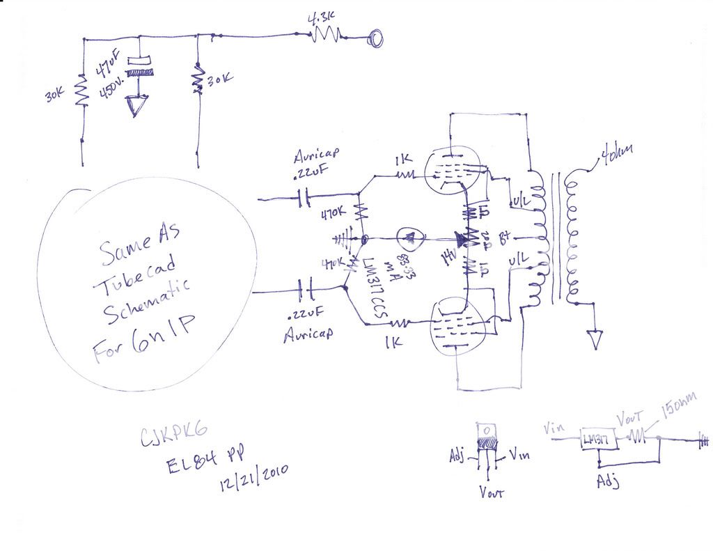
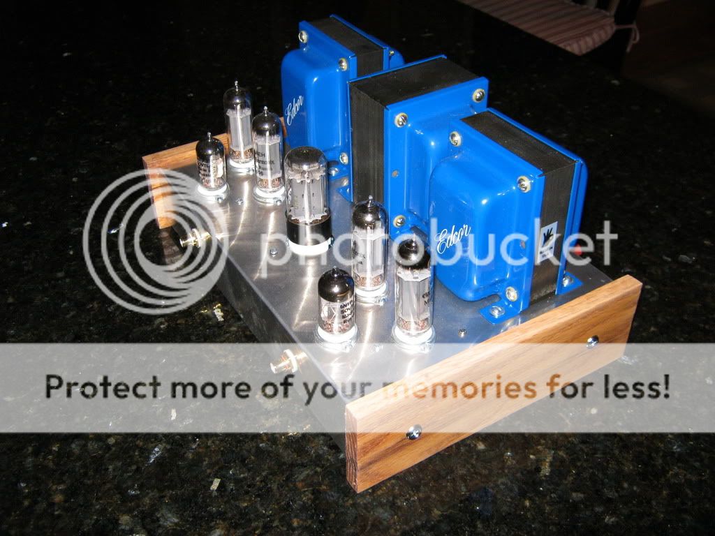
Essentially what I did...plus replaced the 340 ohm resistor on the front section of the 6n1p with a red LED. Sounds Fantastic. Iron is all Edcor with broskie PS-4 PSU using a 5ar4 rectifier.
Thank you for the schematics - I'll have a go at that - removing the cathode bypass is first up as shoog says, then the ccs. I'll try the led too - I get about 2v across the 340r right now so it's a straight forward swap...
If you wanted to double-protect cjkpkg's output stage then you could add say a 30V zener across the 317 to 0V, and put wiper open-circuit protect resistors on the pot.
I find the coupling method between the 6N1P stages to be interesting, I have not seen it in other schematics. Does anyone know of the pro's and cons of this method of coupling versus DC coupling, or versus having the split load inverter self-biased?
I find the coupling method between the 6N1P stages to be interesting, I have not seen it in other schematics. Does anyone know of the pro's and cons of this method of coupling versus DC coupling, or versus having the split load inverter self-biased?
Have not seen schematics of my Pyramid amps?
Yes I have, but do not remember seeing this coupling method. Pro's and cons are?
One advantage I can see is the ability to easily set DC operating conditions at idle.
One advantage I can see is the ability to easily set DC operating conditions at idle.
Last edited:
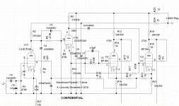
Cons are higher number of parts needed (R6, C5, R8 in Pyramid-VII-M). 😀
Concertina has high input resistance and low input capacitance, so I even omitted that shunting capacitor: anyway I had a Zobel compensation network there, so resistance of the voltage divider and input capacitance of Concertina formed one more Zobel in parallel with the existing one. 😉
Main advantages are: flexibility in choosing of working point, and higher stability on low end. Coupling all tubes in the amp directly (well, except output tubes) I stabilized working point of all of them at once feeding screen grid of the 1'st tube from tail of the LTP driver.
Here is one more time my Pyramid attached, for the reference.
Attachments
Thanks for that. I have the Pyramid 8 schem and couldn't see it, because the cap was gone 😀 Still, its not a common coupling technique, but is definitely worth remembering. With direct coupling, with no divider or cap, it is difficult to try different tubes due to the changing DC conditions.
If one put a trimmer resistor in place of the lower resistor of the voltage divider in the Tubecad circuit, one could easily tweak the DC conditions. Probably no point in tube-rolling, the 6N1P certainly sounds very good to me, I run it in 2 out of 3 small PP amps I have.
If one put a trimmer resistor in place of the lower resistor of the voltage divider in the Tubecad circuit, one could easily tweak the DC conditions. Probably no point in tube-rolling, the 6N1P certainly sounds very good to me, I run it in 2 out of 3 small PP amps I have.
Thanks for that. I have the Pyramid 8 schem and couldn't see it, because the cap was gone 😀 Still, its not a common coupling technique, but is definitely worth remembering. With direct coupling, with no divider or cap, it is difficult to try different tubes due to the changing DC conditions.
Yeah, and I got lots of criticism from people who think by patterns. 😀
If one put a trimmer resistor in place of the lower resistor of the voltage divider in the Tubecad circuit, one could easily tweak the DC conditions. Probably no point in tube-rolling, the 6N1P certainly sounds very good to me, I run it in 2 out of 3 small PP amps I have.
Good idea, I would not leave that pot in place under a voltage, in sensitive AC position, being afraid of noises.
Anatoliy you fly so far over my head at times... 😀
Some parts I think I understand but others I need help with. I take it that the voltage divider of R6 and R8 is there to allow you to bias the cathodyne at a different voltage from the plate voltage of the prior stage (presumably the optimum for one stage is not the optimum for the other).
I take it that the tail of the differential is used for the screen supply because it is convenient and stable much like an output stage cathode is a convenient place for a heater bias. The 120u cap to ground is, I assume, to decouple any signal or other AC from the screen.
Now here is where I am floundering a bit. What is the purpose of the bypass cap C5 and the filter network of C4 and R4? Is it for closed loop stability? I what way is performance reduced if C5, C4 and R4 are eliminated?
Thank you for your educational efforts.
are we off topic, or still on topic ?
Yes, we are! The question was, why this nice little amp has a voltage divider between forst stage and phase splitter, and why it was not seen before. The answer is, it was seen before, at least in my Pyramid amplifiers.
Anatoliy you fly so far over my head at times... 😀
Some parts I think I understand but others I need help with. I take it that the voltage divider of R6 and R8 is there to allow you to bias the cathodyne at a different voltage from the plate voltage of the prior stage (presumably the optimum for one stage is not the optimum for the other).
Exactly!
I take it that the tail of the differential is used for the screen supply because it is convenient and stable much like an output stage cathode is a convenient place for a heater bias. The 120u cap to ground is, I assume, to decouple any signal or other AC from the screen.
Yes. on DC it is kind of a common mode cathode follower, so servo feedback was taken from it's tail.
Now here is where I am floundering a bit. What is the purpose of the bypass cap C5 and the filter network of C4 and R4? Is it for closed loop stability? I what way is performance reduced if C5, C4 and R4 are eliminated?
C5 is to compensate an open loop gain lost on the voltage dividet that we need to shift DC level, actually. For those who are afraid of "sound of capacitors" it may be omitted.
C4 and R4 is a Zobel network for a dominant pole compensation: the amp has nested feedbacks, and one of them is a global one, so without this compensation it is non - stable on high frequency.
Thank you for your educational efforts.
You are welcome,
and sorry guys for OT!
mmmm. I tried to make up the CCS for the EL84s tonight. I used 4 x LM317ahv that I had to hand. Fitted one and used 3 x 100r in parallel to get 33R - my thinking being I would give each tube its own and then tube matching would not be needed.
So I made one up as per the sch shown earlier, with a 1r in series to measure current easily. With 33R I got ~50mA... too much maybe. So then I took out one of the 100R to end up with 50R and I get 39mA. Lovely!
So I go and make up my other 3 CCS, add them in and it all fires up OK, except that I have no sound!!! Can't figure it out! Must be something stupid......
Fran
Hmmm.... What kind of a voltage gain and output resistance do you expect from output tubes if each of them has own CCS in cathode?
If no sound then it almost sounds like there is some feedback loop that is left "open"...Just thinking out loud...
With independant CCS's each cathode would be connected to ground but it would seem that the voltage off each cathode in a push pull pair must be shared?
With independant CCS's each cathode would be connected to ground but it would seem that the voltage off each cathode in a push pull pair must be shared?
Couple your cathodes with a non-polar cap and you should be fine,or just bypass them like a resistor.
Couple your cathodes with a non-polar cap and you should be fine,or just bypass them like a resistor.
Variable bias that is modulated by signal loudness? What is good in it?
OK, so I have some studying to do - never professed to be anything other than a kit man..... 😱😱 
Anyway, back as nature and CCS intended now with 20R across the LM317. Didn't have a 20R pot so that will be for down the line a little. For now, its up and running, the voltages all check out and best of all its sounding great.
After I get a better chance to listen more, I'll post a few impressions.
Thanks to all for the help and prodding.....
- Home
- Amplifiers
- Tubes / Valves
- Unexpectedly good EL84 amp