So I've already exploded two LM3886 chipamps messing with this so before I connect my actual parallel/bridged point-to-point tri-amp system, let me get some thoughts.
My two EI transformers are surplus electronics, unlabeled, very bulky and heavy, putting out 19VAC on their single secondary winding. I've got them wired to a bridge rectifier, feeding into a number of random surplus electrolytics, all rated at least 50V, with a capacitance of... let's say... 25,000uF per rail. I've built dozens of super-low-budget non-regulated power supplies, so I'm confident that I've wired everything up right.
When I test the rectified/filtered voltage with no load, I'm getting +/-55VDC. Either I'm misunderstanding something, or I've discovered free energy. You're welcome, if it's the latter.
With giant heavy cored transformers, do they just keep pumping bits of voltage into the capacitors until the voltage at the caps is scary high? If I connect my whole system (a total of 14 LM3886 chips) will the quiescent load of the chips keep voltages in-line with the stated max input voltages? See, one of my test circuits sat there, staying cool, connected to a speaker, as silent as all my LM3886 amps are, voltages were higher than I was comfortable with... and then I touched the input pin, hoping to hear the 60Hz buzz, and POW, the poor little chip gave up its magic smoke.
I did have a system (only 12 LM3886s) very similar to this running with this exact power supply, and it worked very well until I built a higher voltage supply and let the magic smoke out of every chip, even the opamps in the active crossover. THIS TIME I'm using sockets for my opamps. And resistors between the power stages and crossover. And I'm using perfboard for the crossover this time. Point to point with opamps is just too fiddly.
There is definitely something wrong here, DO NOT connect your amps before fixing this. Unloaded voltage can be a bit higher than loaded but not that much.
Your confidence that you have wired it correctly probably prevents you to see the error ;-)
It seems that you have wired two secondaries in series (38V) and send that to a bridge, that would give 38 * 1.4 = 55V ballpark. Checks out.
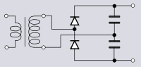
What you need to do is wire the two 19V secondaries in series, mid point to ground, and the ends into a two-phase rectifier (fancy name for two diodes) or two of those for +/- supplies. A bridge would work also, but you need to ground the secondaries midpoint.
That will give you about 19 * 1.4 or approx 26V.
Good luck!
Jan
Your confidence that you have wired it correctly probably prevents you to see the error ;-)
It seems that you have wired two secondaries in series (38V) and send that to a bridge, that would give 38 * 1.4 = 55V ballpark. Checks out.
What you need to do is wire the two 19V secondaries in series, mid point to ground, and the ends into a two-phase rectifier (fancy name for two diodes) or two of those for +/- supplies. A bridge would work also, but you need to ground the secondaries midpoint.
That will give you about 19 * 1.4 or approx 26V.
Good luck!
Jan
Last edited:
Have you check the primaries : 110 or 230 VAC ?
110VAC => 19VAC
230VAC => 230/110*19*1.41 - 1 (bridge) = 55 VDC ...
Yes good point!
Yup. I did mess up the wiring.
I connected one of the ends of the secondary coil circuit to the center rail of the capacitor.
Now, with the center of the secondary rail circuit connected to the ground rail, I have a happy, safe +/-27VDC. THANK YOU!!!
I don't understand how I could get peak-to-peak more than 100 volts out of secondaries that are putting out 55V.
I don't understand how I could get peak-to-peak more than 100 volts out of secondaries that are putting out 55V.
I presume you inadvertently ended up with a voltage doubler like this:
https://en.wikipedia.org/wiki/File:Bridge_voltage_doubler.svg
Attachments
Last edited:
- Status
- This old topic is closed. If you want to reopen this topic, contact a moderator using the "Report Post" button.