amp the OT is not wound symmetrically from the center to the tips i get 45 ohm and 68 ohm.
2 options cross my mind..
1- pott the transformer again cos maybe it warmed up and the isolation melted..
2-using the OT without using the center tip maybe as class a amp?
can it be done?
thanks for the suggestions
David
2 options cross my mind..
1- pott the transformer again cos maybe it warmed up and the isolation melted..
2-using the OT without using the center tip maybe as class a amp?
can it be done?
thanks for the suggestions
David
Actually, this is very common in a lot of classic iron where the two sides are not wound bifilar. The side of the CT which is farther from the core will have a higher DC resistance for the same number of turns. If the AC balance at bass and midband is OK, I wouldn't sweat it.
At worst, you might have to do a bit of compensation on one side to stabilize feedback, generally a small cap between the CT and the lower resistance end. Check out the Eico HF87 schematic for an example of this. Dynaco used a cap (iirc, 390 pf) from the screen tap on that side back to the input stage.
At worst, you might have to do a bit of compensation on one side to stabilize feedback, generally a small cap between the CT and the lower resistance end. Check out the Eico HF87 schematic for an example of this. Dynaco used a cap (iirc, 390 pf) from the screen tap on that side back to the input stage.
the thing is...
the man i bought if from told me that the OT is gone...
when i took it home i checked it and found that the winding isn't broken not at the input nor on any of the outputs..
the only abnormality i found was the resistance ratio
i will connect it to a sine wave generator and spectrum analyzer and see the frequency response as well as trying to check from the input output voltage ratio and the output resistance terminal the resistance of the primary..
so you think there is no room for re potting the transformer?
only using feedback to fix the output ratio?
I doubt if anything is faulty with the transformer. There are two ways of achieving balanced resistances (ideal). Either you wind bifilar, or you use vertical sectioning, rather than horizontal, which means using a split bobbin, so that each PP section is identical. A short-circuited turn will be immediately apparent on an AC test as extremely poor performance.
No, I wasn't clear, sorry. The output ratio may very well be fine. I was merely explaining why the DCRs might be different in a perfectly sound transformer. Which yours may well be; EC8010 summed up better than I could. My other suggestions were for ways of doing compensation for a lack of perfect AC balance at the extreme top end due to the winding method, not for fixing a faulty transformer.
If it is faulty, you need to rewind it- repotting won't help.
If it is faulty, you need to rewind it- repotting won't help.
SY said:My other suggestions were for ways of doing compensation for a lack of perfect AC balance at the extreme top end due to the winding method
Hello SY: I'd be interested to see the circuit of a commercial amplifier that owns up to needing to compensate for the poor winding balance in its output transformer...
It's frightening, but most output transformers are wound unbalanced.
Take a gander at the Eico HF87 that I mentioned; the schematic from Photofacts is up on the web somewhere. And there's that unbalanced feedback cap in the ST-70 (the Dyna circuit); it's HF unbalance, not midband that's being compensated by the cap in both these commercial examples. The midband imbalances only seem to get taken care of in amateur designs, usually doing something like deliberately unbalancing the operating points of the output tubes, or in commercial amps with adjustable AC balance.
In the latter case, adjustment instructions typically call for minimizing output with a common-mode 60 Hz signal, which in effect compensates for any OPT imbalance (at least it does at 60 Hz).
In the latter case, adjustment instructions typically call for minimizing output with a common-mode 60 Hz signal, which in effect compensates for any OPT imbalance (at least it does at 60 Hz).
thank you
here is the schematic of the eico amp if someone is interested.
i will tri the ac test at http://www.geofex.com/ampdbug/outtrans.htm
i hope i dont have internal shorts inside...🙂
here is the schematic of the eico amp if someone is interested.
i will tri the ac test at http://www.geofex.com/ampdbug/outtrans.htm
i hope i dont have internal shorts inside...🙂
Attachments

here is the schematic of the eico amp
Todah rabah!
The 470pF cap is the one I was talking about. Note the unbalance in the DCR. That notwithstanding, these output tranformers work superbly (I think they were sourced from Brooks).
🙂 thanks to you!!🙂 iv done the test and..
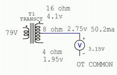
i did the test from <http://www.geofex.com/ampdbug/outtrans.htm> and got this results for the 50w 2xel34 OT: (i didn't had the neon and connected the circuit like shown in the picture)
input voltage: no load 3.14v 50 hz from a 65 volt transformer with variac on its input(the minimum on my variac was 5v so i had to...)
when connected to the 8 ohm tap it drooped to 2.75v with 50.2ma (no current limiting resistor)
the voltage in the primary was 79v and divided symmetrical between the center and tips.
after calculation the primary impedance is approx 5k ohm.
the voltages in the other tips where:
4 ohm=1.95v
8 ohm=2.75v
16 ohm=4.1v
seems ok or is the OT dead?
have great day🙂 and again "toda raba"🙂
Attachments
good news abut the other one...🙁
i think the 100w 4xel34 has an internal shorts..
the input voltage drops from 3.14 to 2.94 with 37.3ma on the 8 ohm tap so far so good but!
with 3.14v input i get on the primary tap to tap only 30v..
after calculation i get that the input impedance is 750 ohm???
much to low...
maybe it has something to do with the 50hz frq? the higher the frq i should get higher impedance and higher voltage over it...
is this one dead or maybe just have a crocked spectrum response?
- Status
- Not open for further replies.
- Home
- Amplifiers
- Tubes / Valves
- uneven wound 50w OT 2 ideas...?