Does the experts think those 1.3w was wrong choice and could that be the problem too?
What exactly are you trying to achieve... what problem do you see or think you see?
Do you want the rails to be exactly the same... which is really a non issue but it can be done just by tweaking the divider network.
The Zeners only dissipate 80 milliwatts or so and that does mean a lower wattage part may give better results on paper and be a bit more stable with regard to temperature change. It wouldn't alter the tracking between the rails though.
Would like them to be some 0.5-1v max.. over 2v difference seems much and if its pushing 84v it seems high (too high)
Do you mean tweaking the 1.8meg or the 33k?
Where and how should i solder in trimpot? In series / or and with an extra resistor like mentioned before?
Sorry if i sound confusing.
In my smaller Nad 216 that uses the same kind of regulator i have spot on for both channels maybe thats why im thinking the big brother could do the same hehe
I have some 300mw 27v diodes from nxperia, could also try them.
I have some 300mw 27v diodes from nxperia, could also try them.
OK, so there are things you can try. Firstly remember that the negative rail is determined only by the Zeners and so you have little control there.
You could try the 0.3W devices and see how the rail changes with temperature as well as the absolute voltage when compared to the 1.3 W parts. Make notes of results as its easy to forget what happens.
Tweaking the positive rail can be done by altering any of the resistors in the divider network but remember the changes you are after are really quite small and so we only want very limited adjustment range.
If you make R712 a 30k instead of 33k and also add a 4k7 (or5k) preset in series then you have a range of 30k to 35k which would give a voltage of approx 76V to 88V. The 1.8meg should be removed if you do this.
Contentious view I don't see mentioned yet:
If both regulated rails are both stable (non-oscillating ) across their load range, then the nominal DC output voltage imbalance Does.Not.Matter.
Understanding why it might be asymmetric may help understanding for OP, and all of us, and there are many great posts above covering that.
But - the effect on the amplifier it powers, and final enjoyment ? Nothing, none on %thd or any other metric -short of asymmetrical clipping. And that doesn't much matter, because (however you look at it) - you are into clipping....
Ensure your regulators are always stable, and clean in output under load first - and always. A small % Vdc imbalance is nothing in comparison ( a watt or two short from nominal output? fuggedaboutit..)
Last edited:
- in short: everything is fine with Zeners. You have -81.5VDC - it is super-good-close to nominal -82 VDC. There is no need to change anything.Does the experts think those 1.3w was wrong choice and coukd that be the problem too?
A little different positive voltage may confuse you, but in general it ok too.
Have you measured the resistance of R712 and R713? If no then forget about that power supply, it is ok.
Last edited:
OK, so there are things you can try. Firstly remember that the negative rail is determined only by the Zeners and so you have little control there.
You could try the 0.3W devices and see how the rail changes with temperature as well as the absolute voltage when compared to the 1.3 W parts. Make notes of results as its easy to forget what happens.
Tweaking the positive rail can be done by altering any of the resistors in the divider network but remember the changes you are after are really quite small and so we only want very limited adjustment range.
If you make R712 a 30k instead of 33k and also add a 4k7 (or5k) preset in series then you have a range of 30k to 35k which would give a voltage of approx 76V to 88V. The 1.8meg should be removed if you do this.
Ok will it be R712 or R718 i do this with?
I have some 5K trimpots (blue sealed ones meant for biasadjustments)
Edit: i read too fast, i saw now you mean R712. Thanks
Last edited:
- in short: everything is fine with Zeners. You have -81.5VDC - it is super-good-close to nominal -82 VDC. There is no need to change anything.
A little different positive voltage may confuse you, but in general it ok too.
Have you measured the resistance of R712 and R713? If no then forget about that power supply, it is ok.
Whole PSU are replaced with new parts, the mentioned 33K are 1W,, Halcro and think those were also 0,1% tolerance.
Contentious view I don't see mentioned yet:
If both regulated rails are both stable (non-oscillating ) across their load range, then the nominal DC output voltage imbalance Does.Not.Matter.
Understanding why it might be asymmetric may help understanding for OP, and all of us, and there are many great posts above covering that.
But - the effect on the amplifier it powers, and final enjoyment ? Nothing, none on %thd or any other metric -short of asymmetrical clipping. And that doesn't much matter, because (however you look at it) - you are into clipping....
Ensure your regulators are always stable, and clean in output under load first - and always. A small % Vdc imbalance is nothing in comparison ( a watt or two short from nominal output? fuggedaboutit..)
Can i somehow test if they’re stable and without ocilliation?
I have a scope and signalgenerator but only up to 5mhz and it’s cheap one.
Everybody: thanks for all help! I haven’t had time over to dig into the amp today but hopefully tomorrow.
I can't really see this oscillating simply for the fact there is to much decoupling dotted about everywhere. Oscillation just couldn't happen as far as I can see.
If you set your scope to AC coupling and connect it across the rail then you should see just a straight line trace with no unwanted noise present. Set the V/Div to a something like 1 or 5 millivolts/Div.
If you set your scope to AC coupling and connect it across the rail then you should see just a straight line trace with no unwanted noise present. Set the V/Div to a something like 1 or 5 millivolts/Div.
I must have a crappy scope (just a handheld one) but i dont find v/division. But i find ac/dc coupling.
Anyway as you said before i think myself there is no distorted signal to talk about.
I’m thinking about dissaemble the whole amp (previous owner smoked) and it stinks and the whole psu bord is so hard to get too that im thinking doing everything i planned (some more caps on each channel, mount soma heatsinks Etc etc (new cables) and when im done with that i continue with this.
I will do a schematic and draw up how i will connect the trimpot and if i get a thumbs up from you i’ll continue.
And yes Mooly if you’re thinking i have som Nad amps etc you’re right, have now 4 Nad amps, and 2 preamps.
By working on this atleast i feel i learn some things along the way.
These amps were new when i was a kid but i could never afford them and i just thought it would ve fun to see how far you can go by changing parts in pure performance and in my ears it pays of a lot!
I do really like my Amps a lot and so grateful for all help when i get stuck and i try to update you all as soon as i know more.
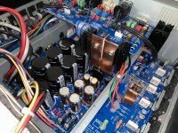
To light up the thread i also put couple of pics hehe
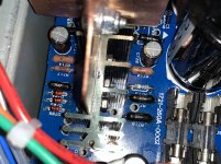
The black resistors are the 33K and the blue above is the 1.2M.
Also can be seen the zeners and the 2 pairs of sc2240/sa970 (plus all other things i’ve been doing so far)
The black resistors are the 33K and the blue above is the 1.2M.
Also can be seen the zeners and the 2 pairs of sc2240/sa970 (plus all other things i’ve been doing so far)
Attachments
That's looking good 🙂
Don't know what to say in the scope... V/Div is a bit like the setting the range on a DVM, its a vital number to know. If a signal spanned 1 square in height on the display is it 1V, 1kV, 1 millivolt and so on......
Maybe it is auto ranging if it's one of these little popular do-dahs but it should then say on the display what it has set itself to.
Smoke contamination can be bad, I used to see that all the time with TV's, sometimes to the point of tar dripping from high voltage leads... it can reach those kind of levels.
For general grime a board of 'pure electronics' (so no mechanical parts or delicate tuned coils) can be washed in hot soapy water and rinsed and dried. They come up like new.
Hehe, not that bad but it smells. Got it from Norway this amp.
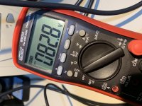
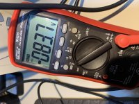
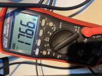
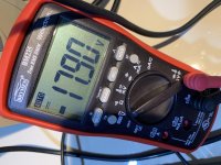
Anyway, after been now playing music on it i decided to check voltages again after warm up (first time i did it all components were ”broken” in 10-20min perhaps.
Here is the result from now, looks better i think??
Note: voltages are taken right/ left board input, and just by the op amps, not sure if it makes a difference. So we are clear, not directly on the psu/regulator. Some 20-30cm cable/tracks between.
Attachments
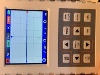
You would have to read the manual for the scope. You can test it with a DC voltage from a battery with a pot wired across the battery. In other words a variable voltage supply from say 0 to 9 volts. See how it handles that and compare the result with a DVM.
The display says X1 and 5 volts which could mean 5 volts per division. The X1/X10 button might (don't know for sure) increase the sensitivity by 10 thus making it 0.5V/Div.
The regulators are low current and so wiring length will make little difference as any volt drops due to resistance will be very small.
- Home
- Amplifiers
- Power Supplies
- Uneven voltage from regulator?