Left hand circuit shows two series resistors across a DC voltage. The right hand diagram shows the same, but with a separate AC source simply using one of the conductors of the other circuit for its own connectivity. There is no ground, you have two independent voltage sources operating with no interaction. The AC source feeds into the left hand 100 ohm. The DC source is the same as in the left diagram.
Is it supposed to be like that ? That's how its drawn anyway.
Yes, and the simulator shows a sine wave signal on the scope on the left hand side next to the 100 Ohm resistor on the bottom, and a constant current on the right hand side under the 100 Ohm resistor.
Shouldn't there be a ripple current on the right hand side? After all current sources are susceptible to 'noise' which consists of a current which varies slightly for DC.
My question is if the simulator is 100% accurate in modelling the effects.
In exactly the same way, you can have a DC voltage and an AC voltage added together in a circuit. Nothing startling or hard to understand about that either, really. It's just unfamiliar.
Well yes, that makes it clearer.
So I have to search for "noisy DC current circuit" .
Why does it not show in the scope of the simulator in the DC circuit? It should show up as noise in the DC current?
Shouldn't there be a ripple current on the right hand side? After all current sources are susceptible to 'noise' which consists of a current which varies slightly for DC.
My question is if the simulator is 100% accurate in modelling the effects.
You have to remember that all voltages are measured 'with respect' to another point. The current flowing in the DC path at the right is unaffected by the sine wave at the left.
A good analogy would be to consider a small 3 volt torch. The torch is on, the bulb is lit and passing say 0.5 amps. If you now connect any point of that torch circuit to say (and lets be silly) a 175,000 volt power line then the torch behaves exactly the same way with identical currents and voltages flowing. If we then connect that power line in series with a conductor in the torch then again, nothing changes in the DC path.
It doesn't change because (as in your diagram) there is no reference point to measure against.
You need to grasp this 🙂
These simulations show your circuit with 'ground' or our point of reference in two different locations.
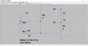
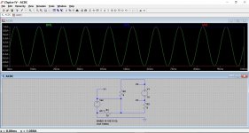
Picture 1. First the basic circuit.
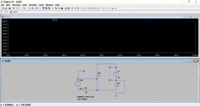
Picture 2. Then we have the actual voltages showing V1 and V2. V3 is 'ground' and so zero.
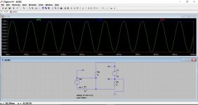
Picture 3. Now we have the currents in R1, R2 and R3. Notice the current in R1 is 1 amp peak sinewave because the voltage source is set to be a 10 volt peak sinewave. Across 10 ohms this gives 1 amp. Notice how there is zero effect on the DC current in R2 and R3.
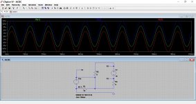
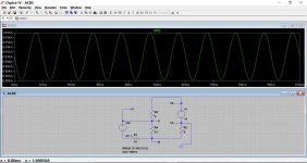
Picture 4. Now we move are point of reference or 'ground'. Look at the picture. Now we have the AC voltage as showing as a 10 volt peak sinewave and it modulating or varying all the other voltages. This is because we have changed our point of reference. Everything is now changing with respect to this point.
Picture 5 Now look carefully at the currents. The current in R1 is varying, its our 1 amp peak sinewave but the currents in R2 and R3 are unaffected.
These simulations show your circuit with 'ground' or our point of reference in two different locations.
Picture 1. First the basic circuit.
Picture 2. Then we have the actual voltages showing V1 and V2. V3 is 'ground' and so zero.
Picture 3. Now we have the currents in R1, R2 and R3. Notice the current in R1 is 1 amp peak sinewave because the voltage source is set to be a 10 volt peak sinewave. Across 10 ohms this gives 1 amp. Notice how there is zero effect on the DC current in R2 and R3.
Picture 4. Now we move are point of reference or 'ground'. Look at the picture. Now we have the AC voltage as showing as a 10 volt peak sinewave and it modulating or varying all the other voltages. This is because we have changed our point of reference. Everything is now changing with respect to this point.
Picture 5 Now look carefully at the currents. The current in R1 is varying, its our 1 amp peak sinewave but the currents in R2 and R3 are unaffected.
Attachments
AC is not the same thing as noise. Noise is an unwanted thing. The AC in an audio amplifier is not noise, it is the music or speech that we are trying to listen to.So I have to search for "noisy DC current circuit" .
Not as noise - you have a sine wave AC. And, as Mooly has been explaining to you, the last circuit you're modelling has completely separate AC and DC loops - they do not interact in any way. My guess is that this was in fact not your intention, i.e, you wanted the voltages to add?Why does it not show in the scope of the simulator in the DC circuit? It should show up as noise in the DC current?
Take a look at the attached picture (an LTSpice screen capture). I put an AC and DC voltage source in series. Both of them are in the same loop, so now they have to interact with each other.
The blue line in the plot is the DC alone (1 volt, V2). The green line is AC plus DC - notice where zero volts is in the graph, the AC has been lifted up and is "riding on the shoulders" of the 1 volt DC.
The 1k resistor in the circuit will now "feel" both the AC and DC sources together acting on it.
-Gnobuddy
Attachments

Mooly I think I get it.
A small modification to make the circuit easier for me to understand:
In your picture 1, the basic circuit, if I replace the AC current with a DC one, and one R1 with a variable resistor and rapidly vary the resistance in the left hand circuit (simulating a half-sine wave dc signal) for example, the current in the left hand circuit will vary because the resistance is varying.
In the right hand circuit, however, the resistance does not change, so there is no effect.
As someone said, it is two circuits sharing a common wire. There must be some microscopic ac induced effects, but in no way will the signal from the left hand circuit transfer to the right hand circuit.
I am not sure, however if the common section of wire will show the superimposed AC signal on DC when checked with a scope.
Mooly I think I get it.
A small modification to make the circuit easier for me to understand:
In your picture 1, the basic circuit, if I replace the AC current with a DC one, and one R1 with a variable resistor and rapidly vary the resistance in the left hand circuit (simulating a half-sine wave dc signal) for example, the current in the left hand circuit will vary because the resistance is varying.
Yes

In the right hand circuit, however, the resistance does not change, so there is no effect.
Yes
As someone said, it is two circuits sharing a common wire. There must be some microscopic ac induced effects, but in no way will the signal from the left hand circuit transfer to the right hand circuit.
I am not sure, however if the common section of wire will show the superimposed AC signal on DC when checked with a scope.
This is where simulation and real world measurements will differ. In the simulation, all the wires have zero resistance. In a real example all the conductors would have a small resistance.
So here is the basic circuit with a new 'resistor' R4. This is now simulating the effect of the piece of wire between points A and B as having 0.1 ohms resistance.
The current in the left hand circuit has now fallen very slightly because the voltage source sees 10 ohm + 0.1 ohm.
The previously steady current in R2 and R3 is now being modulated by the tiny voltage that appears across the piece of wire (R4) as you can see. This shows the current in R2 (R3 is similar). Look at the scale at the left. Its almost pure DC but with a tiny variation.
Attachments
- Status
- Not open for further replies.
- Home
- Amplifiers
- Solid State
- Understanding Transistor amplifier with an online simulation