There is an aspect of rating transistors SOA I do not understand for class AB amplifiers.
On the SOA graph,
Ic = Output Voltage / Load Impedance
Vce = Rail Voltage - Output Voltage
(for Load Impedance approximately real and constant). Plotting Ic vs. Vce is called the "load line" I believe. When Vce is small, Ic is high (near the rails), and when Vce is large (near zero output) Ic is low.
For a transistor with a constant collector current, this load line is plotted on the SOA graph. It should remain under the SOA graph, properly derated for temperature at constant power dissipation.
For sinusoidal rather than constant Vce, high Vce only occurs near zero output. Therefore for a purely resistive load, the part of the SOA near second breakdown occurs only for the brief period near the zero crossing. So one would expect that the useful SOA would be somewhat better than the DC prediction.
However, with reactive loads, it is possible to have high current near the zero crossing because of the lead/lag of Ic relative to Vce. How does one account for this? Is using the DC prediction for SOA typically considered safe for this, or is there some other criterion?
Is using the DC prediction for SOA typically considered safe for this, or is there some other criterion?
Keep in mind SOA as a thermal dissipation ability and just simulate dissipation at the reactive load.
Andrew T told us that sum of DC soa current rating of all parallel output transistors at the rail voltage they are subject to predicts capability to perform class ab amplification at a certain wattage (current) if the heat sink is near the 25 C tests are done at.
This was an experience based rule of thumb having nothing to do with the details of the soa test. Actual speaker currents are much higher, he said, than the resistive load amps are rated for wattage at.
Looking at class AB amps that are successful in the marketplace, ie don't blow up during the warrenty period, those follow this rule pretty closely. Amp repairmen have asserted on PA forum that 4 brands of PA amp were pretty reliable at rated wattage 24/7, at least the ones from the nineties: Crown, QSC, Peavey, Yamaha. If you look at their products from that era, they follow this rule for wattage rating.
Last edited:
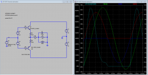
Based on your simulation, it seems like three pairs of transistors would be needed to operate safely at +/-72 V. At peak Vce (72V), the Ic is 6 A. Looking at the data sheet, the SOA current is 2.5 A. So 3 pairs would be barely adequate. Is this about right?
Is this about right?
Yes, highly likely, but doesn't forget safety margins for worst-case reactive load.
For hard driven amp i'ld put 4-5 pairs or design in G/H-class OPS with switched/tracking supply rails.
In case of non-diy professional use there are no way to override TD- or D-class in low-freq operation while for midband and high-freqs it can be built in classical AB-class.
At peak Vce (72V), the Ic is 6 A.
~8A in the given not a really bad case.
So keep your fingers crossed.
Last edited:
For an 8 ohm load? 72V gives 9A in the limit. Not that the amplifier would get to 72V peak output perhaps, but limiting conditions are precautionary.
For a load line I sometimes consider a 45 degree phase shift. That generates an ellipse instead of a straight line on the voltage:current (load line) graph. It's where the maximum of the current which arises which needs to be protected.
For reliability I would check that the ellipse is handled with the DC power level. Obviously, a reactive load line is frequency dependent but the SOA limits don't often allow for much safety above the DC level- and usually, the SOA graphs are specified for single cycles. Although the peak current at zero volts can be calculated (easily) without constructing a load line.
Last edited:
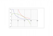
and a graph (as I only had to mod an existing one).
I'd say from the red curve you need 4 pairs (at least) of MJL3281A's compared with a single one (blue line). But you can consider what frequency the load line is at compared with SOA data. It's just that repetitive SOA data is not available, usually. I think the "DC" data is actually only for single 1s pulse.
Green curve is 45 degree load line.
Peak current is 9A/root 2 at the zero crossing (72V). Only half the cycle plotted.
Attachments
Last edited:
- Home
- Amplifiers
- Solid State
- Understanding SOA