Hi, so I was reading this thing:
http://www.tubelab.com/SimpleSE_design.htm
I'm trying to figure out how to design an amp myself, so I started following along with the reasoning presented.
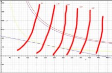
So, I graphed myself a load line using a 5k output transformer and 450 volts total B+. I marked the Y axis point at 90 mA (450/5k). I marked the X axis point at 450 volts. Cool. This should be the line on which my tube can operate along, right?
So, say I'm aiming for 30 watts of dissipation. I drew the line for that, representing all the points that would cause 30 watts of dissipation. Alright. Now, for me to find a place where I can dissipate 30 watts, I need to look for an intersection with my load line, right? This doesn't seem possible with this loadline.
Here's my graph. The red line is a 30 watt line. Purple line is 28 watts. Yellow line is 10 watts. It seems to me like the only operating points I'll get will be near 10 watts...
I must be doing this wrong. Help!
Thanks")
http://www.tubelab.com/SimpleSE_design.htm
I'm trying to figure out how to design an amp myself, so I started following along with the reasoning presented.
So, I graphed myself a load line using a 5k output transformer and 450 volts total B+. I marked the Y axis point at 90 mA (450/5k). I marked the X axis point at 450 volts. Cool. This should be the line on which my tube can operate along, right?
So, say I'm aiming for 30 watts of dissipation. I drew the line for that, representing all the points that would cause 30 watts of dissipation. Alright. Now, for me to find a place where I can dissipate 30 watts, I need to look for an intersection with my load line, right? This doesn't seem possible with this loadline.
Here's my graph. The red line is a 30 watt line. Purple line is 28 watts. Yellow line is 10 watts. It seems to me like the only operating points I'll get will be near 10 watts...
I must be doing this wrong. Help!
Thanks
An externally hosted image should be here but it was not working when we last tested it.
rockgardenlove said:I must be doing this wrong. Help!
Your loadline is a resistor load load, not a transformer load. Transformers do not drop so many volts.
What you need are the tube curves. Say, for instance, that there is a -20V curve that hits 280V at 110mA. Use that as a starting point, bias the grid to -20V, apply a B+ of 280V, ground the cathode. Your load line will be parallel to the one you drew, but it will run through that point. Then you will be dissipating 30W.
Attachments
- Status
- This old topic is closed. If you want to reopen this topic, contact a moderator using the "Report Post" button.