the woofer at port resonance will requiere less power to function at that frequency.
i think that's why you see a dip in resistance at that point (not sure though, i'm too lazy to reference)
dont think of the ported system as a system on its own but rather a mechanical affiliate to the woofer itself.
the air in the port is moved easiest when a certain frequency is present within the loaded chamber (box frequency) and that's why you see less distortion at that point since the woofer doesn't have to work against (a wall) but rather is worked with.
also why is unloads below that point.
edit: does that make sense? not sure...
Vaughan said:Noah, thank you for posting. There is one thing that you brought up which I don't fully grasp.
According to the essay on porting (home theater hifi) , the driver will be moving the least at resonance. The port will be doing all the work.
So I thought that since the port is sucking air so forcefully through the internal air pressure at and around Fb, that it would counterbalance the excursion from the driver and "cancel" the movement to a degree.
You say that that isn't the case. But then where does the low distortion come into play in a ported system ? I had always thought that the driver wouldn't be working as hard at resonance.
I am really confused at this point.
--Sincerely,
I don't get why you are confused. In the statement above you have got the vent action spot on. As you said, the vent is cancelling the movement of the driver to a degree. The vent is doing all the work. Therefore the driver is moving the least.
exhausted mule said:the woofer at port resonance will requiere less power to function at that frequency.
i think that's why you see a dip in resistance at that point (not sure though, i'm too lazy to reference)
That's not quite right really.
At resonance the impedance is at a minimum level. This means current draw is at a maximum hence power draw is also high.
The dip in impedance is caused by the loading of the cone by the vent.
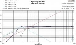
Here are some pictures to talk to also.
This picture is for Dayton DA-175 7" Aluminum Cone in a 27.6L enclosure, with a 2" port tuned to 32 Hz.
The black line is the driver SPL, notice it starts to "roll-off" at 200 Hz.
The light blue line is the SPL produced by the port. Notice the SPL peaks at approx. 32 Hz. Also notice at 900 Hz, the port is producing SPL again and it is effecting the combined response.
The dark blue line is the combined response.
Attachments
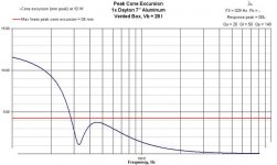
Here is a graph of the driver cone excursion. Notice at the port tuning (32 Hz), the cone excursion is minimal. This is why ported enclosure are said to have less distortion. In this case, you are producing 32 Hz with no cone excursion.
BUT, also notice below the tuning there is huge cone excursion.
BUT, also notice below the tuning there is huge cone excursion.
Attachments
At resonance the impedance is at a minimum level. This means current draw is at a maximum hence power draw is also high.
The resonances of a ported box are at the impedance peaks. The minimum impedance between the peaks is not a resonance.
Noah,
Each mass contributes 12 dB/octave of roll-off. So a bass reflex has two masses acting at the two resonances, the cone and the port, which produces a 24 dB/octave roll-off.
You are speculating again Noah without doing the math, not like an engineer to do this. I resonance is a resonance. The back of the driver does not know what is causing the apposing pressure. An empty TL and a BR will have almost identical impedance curves around the tuning frequencies. My guess is that given two impedance curves plotted from 10 to 200 Hz that you would have a 50/50 shot at telling which is the empty TL and which is the BR. If the impedance curves are almost idential so is the motion of the driver. There is very little difference between the two at low frequencies for small signal input before stuffing is added.
I don’t have a solid intuitive grasp on this one; but there’s one order for each reactive element, which in mechanical systems is a mass or a spring.
The driver has a mass and spring, and the box stiffness and port air mass are two more.
As has been said (I think), each order contributes 6 dB/oct to the slope of the rolloff.
Each mass contributes 12 dB/octave of roll-off. So a bass reflex has two masses acting at the two resonances, the cone and the port, which produces a 24 dB/octave roll-off.
I believe they are quite different. BR is a Helmholtz resonator (mass/spring system), whereas a TL is an acoustic resonator that depends on the speed of sound and the length of the resonant pipe.
You are speculating again Noah without doing the math, not like an engineer to do this. I resonance is a resonance. The back of the driver does not know what is causing the apposing pressure. An empty TL and a BR will have almost identical impedance curves around the tuning frequencies. My guess is that given two impedance curves plotted from 10 to 200 Hz that you would have a 50/50 shot at telling which is the empty TL and which is the BR. If the impedance curves are almost idential so is the motion of the driver. There is very little difference between the two at low frequencies for small signal input before stuffing is added.
MJK said:The resonances of a ported box are at the impedance peaks. The minimum impedance between the peaks is not a resonance.
I know but I was just trying to keep it simple for the guy, he's struggling a bit 😉
The reason he is struggling is that several people are producing explanations that are not technically correct. Then others, like myself, are objecting to these posts. Then the thread degenerated into a my sub is better then your sub discussion.
This stuff is not rocket science. But unfortunately there are a lot of "experts" who have read bogus explanations and are repeating them as factual statements without understanding the engineering/math behind the modeling. If the poster does not understand multi-degree of freedom vibration theory, and done the derivations for these simple systems, then my guess is that the advice provided is based on repeating something read elsewhere that kinda made sense and there is nothing to back up the statements but words. Unfortunately, to really understand one needs to actually do the work.
This stuff is not rocket science. But unfortunately there are a lot of "experts" who have read bogus explanations and are repeating them as factual statements without understanding the engineering/math behind the modeling. If the poster does not understand multi-degree of freedom vibration theory, and done the derivations for these simple systems, then my guess is that the advice provided is based on repeating something read elsewhere that kinda made sense and there is nothing to back up the statements but words. Unfortunately, to really understand one needs to actually do the work.
As was pointed out, at Fb the driver is moving least but working hardest, similar to a stalled motor.
Again, the port air is moving into the enclosure and increasing the pressure just as the driver is trying to push out.
"The resonances of a ported box are at the impedance peaks. The minimum impedance between the peaks is not a resonance."
No.
The high peak is the same as Fsc in a sealed box, the drivers resonance from its own mass on the a spring stiffness which is the sum of its suspension and the box air stiffnesses.
The Fb resonance is the impedance minimum, caused by the drivers restricted motion and lower back EMF.
Below that is the impedance peak from the port progressively acting as a hole in the box, allowing the driver to move freely and develop back EMF.
"I believe they are quite different. BR is a Helmholtz resonator (mass/spring system), whereas a TL is an acoustic resonator that depends on the speed of sound and the length of the resonant pipe.
"You are speculating again Noah without doing the math, not like an engineer to do this. I resonance is a resonance."
I'm not speculating at all. They both resonate, but they are the mechanisms are completely different; a mass/spring resonaqnce could occur in the vacuum of space, but an acoustic TL could not.
As a side point of interest, both are used for tuning intake and exhaust systems in piston engines.
The diameter sets the Helmholtz resonance, same as our vented boxes, and the length sets the acoustic resonance, same as TL's.
Smaller diameter moves the torque peak to a lower RPM, as does greater length.
BTW, I didn't notice any math in your post, just a "My guess...".
"Each mass contributes 12 dB/octave of roll-off. "
No; each mass/spring is 12 dB/oct, each single reactive element is 6 dB/oct.
The electrical analogues are L and C, each of which alone produces 6 dB/oct.
Noah,
The math is described in an earlier post and performed in the Anatomy of a TL article on my site. All you have to do is read. I have seen nothing offered by you other then statements, most of which are incorrect.
I suggest you take two identical masses and two identical springs and connect them in series to ground. Write the differential equations of motion and solve for the resonant frequencies and mode shapes. Look at the values you get and compare them to the single degree of freedom system value. Then explain to me how the minimun in the impedance curve, between the two peaks, is a resonance. You don't understand the basic system dynamics of ported enclosures or TLs.
This is my final contribution to this thread.
"Then explain to me how the minimun in the impedance curve, between the two peaks, is a resonance."
I did, via the driver's motion and back EMF.
What don't you understand about it? If you think it's in error, please explain why.
For the record, since you seem to think you're the only one with credentials here, I *have done the math* - I have a mechanical engineering degree and for the last 20 yr at Lockheed Martin I've been doing structural design and dynamics analysis/testing of space payload structures.
They have a lot more degrees of freedom than we're talking about here.
Hi MJK,
This stuff is not rocket science. But unfortunately there are a lot of "experts" who have read bogus explanations and are repeating them as factual statements without understanding the engineering/math behind the modeling. If the poster does not understand multi-degree of freedom vibration theory, and done the derivations for these simple systems, then my guess is that the advice provided is based on repeating something read elsewhere that kinda made sense and there is nothing to back up the statements but words.
Vibrational theory ? What is that and how can I learn more ? How does it fit into how ported systems work ? Are there any books that one can buy that covers this without turning complicated ?
Perhaps you could explain. At hometheaterhifi, they have an essay which several people have recommended that I read.
http://www.hometheaterhifi.com/volume_5_2/cmilleressayporting.html
What do you think of the essay ?
richie00boy,
I don't get why you are confused. In the statement above you have got the vent action spot on. As you said, the vent is cancelling the movement of the driver to a degree. The vent is doing all the work. Therefore the driver is moving the least.
I got confused because Noah said that the drivers force is not being cancelled and that at tuning the loading of the driver is at a maximum. So I think that seems like the opposite of what I thought. Now you are agreeing with my explanantion.
I don't know. So who is correct and who is not ? 🙂
--Sincerely,
Noah, thank you for contributing to the thread. That goes for everyone here.
I appreciate it.
--Sincerely,
I appreciate it.
--Sincerely,
Vaughan,
I think I see where the confusion is. The vent is doing all the work on the outside air, but the energy for that work is coming from the driver (which after all is the only thing connected to a power sosurce), which transfers it to the vent via the air inside the box.
Again I suggest you read the AVS thread, and get a paddle with the ball on the elastic band.
Otherwise you'll have to spend quite a bit of time with a mechanical vibrations text, assuming you have the requisite math background.
Noah, I don't have background knowledge on this. I am just a hobbyist who wants to learn in depth how these systems work.
I have the Vance Dickasons book which I've read three times and I understand the mechanics of speaker design and operation very well. But the book does not go into detail how ported subwoofers work.
I skimmed through the pages in the thread but please understand that I am trying to ask questions which probably were not addressed in that thread. This is why I made this thread; to answer any and all queries.
I understand that the driver is working in order for the air to be sucked through the port. Understand that. But if the sucked air is reducing the cones motion then surely there is less distortion from the driver ?
Correct ? According to the article I posted, the driver will hardly be moving at resonance and so I assume that distortion is very low at this point. Otherwise where would this llow distortion come into play with a ported design ?
I need to read more books on resonance and as MJK said, vibrational theory. Now I'm not a big math guy, I prefer to understand more empirical (and practical) explanations of things.
I know that math and theory are intertwined, but I would like to understand the theory well. Are there any books which really go in depth on this (and are math-less 😀 )?
Thanks a lot.
--Sincerely,
Vaughan said:I got confused because Noah said that the drivers force is not being cancelled and that at tuning the loading of the driver is at a maximum. So I think that seems like the opposite of what I thought. Now you are agreeing with my explanantion.
I don't know. So who is correct and who is not ? 🙂
--Sincerely,
We are both correct 🙂 I tried to use laymans terms again, hence why I qualified it by saying 'to a degree' cancelling/loading - we both meant the same thing.
I think rather than just confuse yourself reading stuff, and dig deep into maths that will just fry your brain, and given that you still don't get it despite having read Dickason's book, I suggest you quickly knock together a test speaker and hook it up to a sinewave generator (your PC will do) and watch/observe what happens to the cone and vent as you slowly sweep across the bass range.
I also got confused because several people had conflicting opinions on how the system works. 🙂
Heh.
The problem with Vance Dickason is that he only dedicates 3 to 4 lines on ported operation. Nothing else. There are graphs, graphs and more graphs but little techical explanations on the operation.
I also get confused because I read articles and learn from them and then I get told that it's basically wrong. So these things I need to set straight and many of you here have more knowledge on how these systems work.
Hence my need to improve. 😀 I'm afraid I can't knock together a test speaker. I don't have the time unfortunatel, although I do have the time to post here apparently.
Strange, huh ?
--Sincerely,
Also, there is something which I've heard of but don't know what it means exactly. Minimum phase.
I've heard it referenced a number of times in acoustics and in threads pertaining to speaker design. What is minimum phase exactly ?
Is a subwoofer minimum phase ? What does that mean ?
Thanks.
--Sincerely,
I've heard it referenced a number of times in acoustics and in threads pertaining to speaker design. What is minimum phase exactly ?
Is a subwoofer minimum phase ? What does that mean ?
Thanks.
--Sincerely,
Minimum phase would refer to crossover schemes where the aim is to achieve minimum phase shift/difference between drivers. Nothing whatsover to do with vented systems.
- Status
- Not open for further replies.
- Home
- Loudspeakers
- Subwoofers
- Understanding ported systems