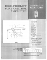
I am study for understand how to draw load lines on triode for now and I though after all I read and apply I have a basic knowledge then came across this RCA schematic and I really do not know how can work, but it works because I built it in one of my amp.
Now talking about the first triode cathode follower with 240v on the plate and a total of 16.5 K resistance on the cathode bring to 14.55 mA current, I cannot even draw a line on the 7025 data sheet where the max current plate is fixed at 4 mA. In this configuration I can see could be good for the 12au7, so I am really confuse, what am I missing? If somebody here can help I really appreciate it.
Now talking about the first triode cathode follower with 240v on the plate and a total of 16.5 K resistance on the cathode bring to 14.55 mA current, I cannot even draw a line on the 7025 data sheet where the max current plate is fixed at 4 mA. In this configuration I can see could be good for the 12au7, so I am really confuse, what am I missing? If somebody here can help I really appreciate it.
Attachments

ok thanks so what is my mistake? My calculation was 240/16500=0.0145 Ampere= 14.5 mA, where I did wrong?
You did not go wrong - the load line is a very poor one. Actually the 240 volts should be reduced by the cathode voltage, but that's less than 10% - just a rounding-off error in tube circuits.
There are lots of nasty surprises in all old engineering. Abuse of cathode followers was widespread in audio electronics.
Ho, ho, yo,
Chris
There are lots of nasty surprises in all old engineering. Abuse of cathode followers was widespread in audio electronics.
Ho, ho, yo,
Chris
You do not have 240 volts over The cathode resistors, but 17.5 volts, so the current is 1mA, as jazbo8 says.
Yes, the DC idling current is about a milliamp. The loadline is (240 - cathode voltage = about 222 volts) across 16K5 Ohms. These values set the X and Y intersects on the load line.
so what would be the plate current?
...and if we do not know the cathode voltage what would be the math for calculate ideal operating point for a cathode follower?
...and if we do not know the cathode voltage what would be the math for calculate ideal operating point for a cathode follower?
The plate current must be the same as the cathode current, and why wouldn’t you know the cathode voltage if you are designing the circuit? 😉
Read this if you have not done so yet: The Valve Wizard -Cathode Follower
Read this if you have not done so yet: The Valve Wizard -Cathode Follower
Still I do not know how draw a load line, I already know the Valve Wizard but is point less for who want to learn, the approach is engineer to engineer like many other website there is really no intent to bring down to basics for help people like me understand.
so maybe load line could be like this?
so maybe load line could be like this?
Attachments
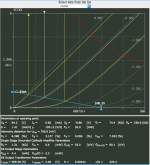
Nope. The default ECC83 in that calculator is more like what you're after. The IDLE (middle white line) is 1ma, max current (left end of load line) is 5ma which it will never achieve in use as a triode can't swing it's plate to 0V due to the Rp of the tube.
This is a excellent resource used by the US military in the 50's... http://sportsbil.com/other/Basic Electronics, Volumes 1-5, (1955).pdf
This is a excellent resource used by the US military in the 50's... http://sportsbil.com/other/Basic Electronics, Volumes 1-5, (1955).pdf
Still I do not know how draw a load line, I already know the Valve Wizard but is point less for who want to learn, the approach is engineer to engineer like many other website there is really no intent to bring down to basics for help people like me understand.
For everything there is some minimum below which it loses all meaning.
That explanation is as basic as can be, it can definitely get way more complex.
Just as an over simplification: that explanation is Tech level; it might be more complex as Engineer level adding quite a few equations instead of the simpler graphical method, and even more, could reach mind numbing Physicist level, which would analyze Electron orbits, detailed electrical field maps, Electron to Proton attraction forces inside the Atom core and 1000 other details.
Thanks God the first Graphical approach is enough for us to design Audio gain stages 🙂
You must study it long enough to "get" it, it can´t be made any simpler.
Personally , lots of people ask me "how to learn Electronics" or "how to design" ... my answer is always : "get an old style, preferrably 40´s to 60´s High School *Physics* book, the part dealing with Electricity and Magnetism "
They say: "what???? 😕 ... I want to learn Electronics, not read some old stuffy book"
Ok, this old book will teach in a very clear way what is: Voltage - Current - conductor - insulator - battery (power supply) - switch - resistor - capacitor - potentiometer - inductance - capacitance - inductor - transformer - watt - power - galvanometer (classic multimeter) - Ohm´s Law - Kirchoff Law - multiple capacitor/resistor/battery value when in series/parallel - frequency - etc.
Once knowing that, Electronics becomes way easier to understand and knowledge is way more solid.
And since you start climbing the stairs from the very first steps, it´s actually easier. 😱
Thanks Fahey and Kodabmx, what at the moment is difficult for me is the understanding of how properly use a tube data sheet for get the best from it, out there there is so many way people use to draw a load line and so many math and calculation that look like is quite impossible to find a unicity way to get the point. I am been trained by Bang&Olufsen engineering dep. and Brionvega engineering back in Italy on the 80's when solid state was taking over the considerate obsolete tube's, and I found the understanding of solid state circuits and projecting more easy because regulated by strict rules. What I'm doing now is building tube amp and is quite easy because with a generator, oscilloscope, voltmeter and spectrum analyzer I always get what I want but I rich the point that getting what I want is not enough anymore I also like understand WHY for example some project sound so good rather then other that are just ok, anyway I am stubborn so I will get it, in the main time thanks to everybody here for your help.
Valvewizard is “point less”?! Perhaps you had too much chianti for the day... 🙂 Seriously, if you had even rudimentary training in electronics, it should be quite easy to follow, or you can ask Merlin to write another book...
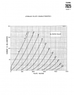
Well you have a graph Anode current versus anode voltage.Still I do not know how draw a load line, I already know the Valve Wizard but is point less for who want to learn, the approach is engineer to engineer like many other website there is really no intent to bring down to basics for help people like me understand.
Then ask yourself what current will flow if the tube is shorted, = Va/R in series with the tube.That's one point of the line at Va=0
Second question, what voltage on the tube with no current ? Without current no drop on the resistor so Va is supply voltage at Ia=0, your other point of the line.Connect the two points with a loadline 😀
Mona
Also, a low mu triode like 6SN7 and the like will be a much better cathode follower IMHO. Lower Zout, more current.
Well you have a graph Anode current versus anode voltage.
Then ask yourself what current will flow if the tube is shorted, = Va/R in series with the tube.That's one point of the line at Va=0
Second question, what voltage on the tube with no current ? Without current no drop on the resistor so Va is supply voltage at Ia=0, your other point of the line.Connect the two points with a loadline 😀
Mona
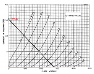
very good info thanks so please can you draw a line here according to this schematic? thank you very much
Attachments

I am study for understand how to draw load lines on triode for now and I though after all I read and apply I have a basic knowledge then came across this RCA schematic and I really do not know how can work
Read this carefully. http://ken-gilbert.com/images/pdf/acpart1.pdf
I would add to Mona's post (#15). Don't get your head stuck with Va=240V. Try Va=50V for a moment then set it back to 240V later.
- Status
- Not open for further replies.
- Home
- Amplifiers
- Tubes / Valves
- Understanding how to draw load lines