I am looking for some clarifications of the components used in this crossover circuit. this all seems pretty simple and straight forward. but I am curious about part interaction and part selection based on those interactions. let me see if i can explain this.
I paid Madisound to design a crossover using there LEAP system. However. due to size restrictions i cannot use the midrange i was going to use. therefore i am trying to reverse engineer this a bit and see if the High pass section can be saved and reused.
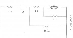
Some basics. the tweeter is 4 ohm and the original midrange was 6 ohms.
So looking at the schematic the 4.7uf and .12mh coil form a basic 12db HP filter. and i think the tweeter is crossing around 6khz or at least that's where the roll off starts on the graph.
I would assume that the 3.3 and 33ohm resistors form a voltage divider to attenuate the tweeter a bit. but i am not sure about the function of the 2.2ohm other then to add some additional attenuation....
or maybe the 3.3 in series with the tweeter is to change the DC resistance/impedance. the tweeter is listed as having a DCR of 3.1 and putting 33 ohms in parallel with that we get about 2.83 ohms. so adding the 3.3 resistor we get 6.13 ohms... hmmmm
Looking at any of the various crossover calcs online i don't get values anywhere near 4.7uf and .12 based on a 4 ohm calc.
So I want to figure out what the resistors are doing and how they affect the circuit.
So X-over experts what can you tell me.
I paid Madisound to design a crossover using there LEAP system. However. due to size restrictions i cannot use the midrange i was going to use. therefore i am trying to reverse engineer this a bit and see if the High pass section can be saved and reused.
Some basics. the tweeter is 4 ohm and the original midrange was 6 ohms.
So looking at the schematic the 4.7uf and .12mh coil form a basic 12db HP filter. and i think the tweeter is crossing around 6khz or at least that's where the roll off starts on the graph.
I would assume that the 3.3 and 33ohm resistors form a voltage divider to attenuate the tweeter a bit. but i am not sure about the function of the 2.2ohm other then to add some additional attenuation....
or maybe the 3.3 in series with the tweeter is to change the DC resistance/impedance. the tweeter is listed as having a DCR of 3.1 and putting 33 ohms in parallel with that we get about 2.83 ohms. so adding the 3.3 resistor we get 6.13 ohms... hmmmm
Looking at any of the various crossover calcs online i don't get values anywhere near 4.7uf and .12 based on a 4 ohm calc.
So I want to figure out what the resistors are doing and how they affect the circuit.
So X-over experts what can you tell me.
Attachments
Last edited:
that's a simple 2nd order xover with l-pad, the 2.2 + 3.3 ohm resistors together make up the series resistor of the l-pad; they're split so that the 2.2 ohms resistor can be tweaked without affecting the frequency response of the filter.
When calculating xover parts values, you can't use the 'nominal' impedance of the driver or Re, you need to look at an impedance curve and use the actual value of impedance at the crossover frequency.
Passive Crossover Network Design
When calculating xover parts values, you can't use the 'nominal' impedance of the driver or Re, you need to look at an impedance curve and use the actual value of impedance at the crossover frequency.
Passive Crossover Network Design
- Status
- Not open for further replies.