Hi Everyone,
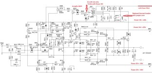
I am trying to learn analog electronics and figured I need to do some 'hands-on' work in addition to the book and lectures. I bought an Adcom 5300 locally for $40 which was listed as not working with both thermal protection lights on. As the lights turn on immediately after plugging the unit it I figured it is an issue with the thermal switch (thermal breaker) since the unit is still cold. I opened it up and checked the 7812 voltage regulator and had good 12v on the output. I started looking at the right channel and measured the voltages on the LM555 chip which seemed reasonable assuming thermal breaker 'open'. The thermal breaker is an Uchiya UP72 85C device and it appears it did not fail "open" but rather had failed as a high value resistor (measured ~14.2kOhm) which effectively forces the transistor Q118 to saturate and turn the output of the LM555 high (thermal LED "on"). I ordered new thermal switches (will take a while) so in the mean-time just put a jumper wire in place and sure enough the thermal LED turned off and I was able to test the R channel is fully operational.
Now, for the left channel I figured I will do exactly the same and sure enough when the unit is in 'stand-by' with 12v coming from the 7812 voltage regulator and all other voltage rails off the LM555 reads 12v on the trigger pin and 'low' on the output and the thermal LED is off. BUT when I turn power on the thermal LED comes on and I have 12v on the trigger pin of the LM555 but the output is high -- actually I'm measuring ~10.8v which doesn't seem right for 'output on'. It is almost as if the voltage is back-feeding from the rest of the circuit. I de-soldered and tested Q010 (2SC1845) next to the thermal LED (it's actually Q019 it's a typo in the schematic) and it tested fine. I also de-soldered an tested Q020 (2SA992) and it also tested fine.
I am having a hard time figuring out how these transistor can back-feed ~10v at the led. Can someone help me out? Thanks a lot!
Attachments
I'm currently working on an Adcom gfa-5300. Having a similar problem as you are. I would like to replace the thermal switches (UP72), as you did, but having difficulty finding where to buy them. There are probably other brands of thermal switches I could use, if only I knew the temperature rating of these. I assume they are normally closed, and open upon a temperature rising. I see on the thermal switch is says "85c". Does this mean these switches open at this temperature? I found a spec sheet on these switches, yet there is no hint as to the trigger temperature.
85c is the trigger to open.
And 85c would be the temperature of the Heatsink.
The Transistor die itself transfers heat to the case
then a mica pad then a heatsink.
So if the heatsink is 85c
without doing the all math
Just assume the Actual transistor junction
is way up at 105 to 115c
So 85c heatsink is pretty typical shut off temp.
Since the transistor is actually cooking pretty good
at that point
Thermal switches borrowed from
industrial equipment / washing machines
many moons ago to switch off amplifiers.
WhiteDragon, Thanks for such a quick response. I figured 85 degrees Celsius is the trigger temperature. It should be an easy task to find a substitute.

- Home
- Amplifiers
- Solid State
- Understanding Adcom 5300