When two ...are too much...
I agree 100% with you...any time that i parallel any device i find the some compromise in resolution...
As i mentioned previously the number of parallel FETs is a compromise between noise, resolution and bass. A single device sounds the most resolved to my ears
I agree 100% with you...any time that i parallel any device i find the some compromise in resolution...
Jonathan or somebody else, where can I find this application note? It seems to that AD has withdrawn this application note.jcarr said:For further study, I suggest reading AN232 from Analog Devices, authored by Walter Jung. Even if you don't use any of the methods proposed in the application note, it should give you some food for thought.
Re: MC stage
 . I would have used a inductor as a last option. The goal is to make a very quite DC voltage because this first stage is very sensitive for noise in the voltage. One other idea is to use R+C+R+C. The advantage of a inductor is that you don't need so big capacitors effective filtering but on the other hand caps are rather cheap and available so what is best?
My suggestion is:
22 ohms + 6800 µF + 22 ohms + 6800 µF = cut frequency 1 Hz / 40 dB/decade => -80 dB at 100 Hz quite OK if the raw voltage already is stabilized.
You can increase the R and also the C, and even the amount of R-C sections.
I think you have figured out that designing electronics is like painting pictures. Many solutions are right, many are wrongrookster said:I am very inexperienced in the area of electrical circuits, but why is the 10H inductor/choke needed? I thought it was a filter, but the circuit is already running of a DC supply anyway. Thankyou for the details on the inductors, but I feel the cost and logistics of ordering 2 of these from Germay to Australia, would make it quite a hassle. Can i substitue something else? Any ideas? If this is the best option, then I will implement it.
. I would have used a inductor as a last option. The goal is to make a very quite DC voltage because this first stage is very sensitive for noise in the voltage. One other idea is to use R+C+R+C. The advantage of a inductor is that you don't need so big capacitors effective filtering but on the other hand caps are rather cheap and available so what is best?My suggestion is:
22 ohms + 6800 µF + 22 ohms + 6800 µF = cut frequency 1 Hz / 40 dB/decade => -80 dB at 100 Hz quite OK if the raw voltage already is stabilized.
You can increase the R and also the C, and even the amount of R-C sections.
6800µF may sound very slow and thick in a simple common source config. While a choke and a small cap may sound much more agile and musical.
Do we talk about the same thing? The filter should be slow in order to reduce noise, but I'll guess you are pulling my leg 
CAPS AND CAPS.
Hi,
Peter,
I am rather at odds with your statement here.
From experience I often prefer oversized filter caps and small value coupling caps.
The bigger PSU caps provide good PSU filtering and ample current reserve , whereas the small coupling caps provide for the agility and musicality... they also tend to sound faster than their larger brethren.
Also, just from listening experience I find the higher voltage coupling caps to sound way better than the lower ones.
Does this go against your own experience?
Cheers,😉
Hi,
6800µF may sound very slow and thick in a simple common source config. While a choke and a small cap may sound much more agile and musical.
Peter,
I am rather at odds with your statement here.
From experience I often prefer oversized filter caps and small value coupling caps.
The bigger PSU caps provide good PSU filtering and ample current reserve , whereas the small coupling caps provide for the agility and musicality... they also tend to sound faster than their larger brethren.
Also, just from listening experience I find the higher voltage coupling caps to sound way better than the lower ones.
Does this go against your own experience?
Cheers,😉
Frank
My remark is only for the specific case of MC input. Current pull is generally low and the 'sound' of electrolityc caps very exaggerated. I would seriously prefer to break a large cap into a smaller + choke. With a reasonable choke you get better regulation and filtration which is easy to calculate.
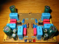
This deceptively simple circuit with a FET and batteries, when implemented well sounds amazingly good. I got mine powered by NiMH batteries and two 100µF BG caps close to the FETs. To my ears it plays better than my Koetsu step-up transformer in every respect but S/N.
cheers
peter
My remark is only for the specific case of MC input. Current pull is generally low and the 'sound' of electrolityc caps very exaggerated. I would seriously prefer to break a large cap into a smaller + choke. With a reasonable choke you get better regulation and filtration which is easy to calculate.
This deceptively simple circuit with a FET and batteries, when implemented well sounds amazingly good. I got mine powered by NiMH batteries and two 100µF BG caps close to the FETs. To my ears it plays better than my Koetsu step-up transformer in every respect but S/N.
cheers
peter
THE TRICKBOX.
Hi,
Peter,
Thanks for the swift reply...
Doesn't come as a surprise to me.😉
Here's what I do in my MC stage:
I use a capacitance multiplier after a voltage reg and have that followed by a ccs sitting almost right on top of the anodes.
In order to bring noise down to inaudible levels I also need to put a few triodes in // which is indeed a necessary evil as you pointed out.
Bass shouldn't be an issue since the RIAA filtering is done in the following stages.
Cheers,
Hi,
Peter,
Thanks for the swift reply...
To my ears it plays better than my Koetsu step-up transformer in every respect but S/N.
Doesn't come as a surprise to me.😉
Here's what I do in my MC stage:
I use a capacitance multiplier after a voltage reg and have that followed by a ccs sitting almost right on top of the anodes.
In order to bring noise down to inaudible levels I also need to put a few triodes in // which is indeed a necessary evil as you pointed out.
Bass shouldn't be an issue since the RIAA filtering is done in the following stages.
Cheers,
peranders: Link to AN232
http://www.analog.com/UploadedFiles/Application_Notes/742022599AN232.pdf
hth, jonathan carr
http://www.analog.com/UploadedFiles/Application_Notes/742022599AN232.pdf
hth, jonathan carr
Thanks. How did you find it? Interesting idea in the application note.jcarr said:
Per: The input-compensated bootstrap idea is admirably suited for DC servos, because yotu normally want a high input impedance anyhow.
Like Jung, I find that having some sort of output buffer in place is a good idea.
The test results of the input-compensated bootstrapped configuration were fine. I don't utilize this concept at the present, but this is primarily because the DC servo circuit that I do use is inverting with bipolar inputs. OTOH, this latter type of circuit has its own unique quirks that need to be taken into account during the schematic design and board layout phases. You normally don't even receive a discount on lunch, let alone getting one for free. 🙂
Should I decide once again to make a high-impedance, non-inverting, JFET input DC servo circuit, chances are that I will revisit the input-compensated bootstrap concept and see if it is possible to advance it further.
Examples of other interesting DC servos would include the simple design that Luxman used in their A901 battery-powered preamp. The "AOC" discrete differential servo that Akihiko Kaneda has been using for his more recent designs is also worth trying, and this is fairly similar to the output buffer section of my own DC servo circuit.
In any case, it is surprising how important the DC servo design is for the overall sonics. As I mentioned in a previous post, you will need to put much more effort into designing a DC servo than you will in selecting an output coupling cap, and there is a commensurately higher risk of getting something wrong. But as far as I can tell, the concept is fine - the actual design and implementation stages are where it is likely that you will stumble.
hth, jonathan carr

Simply great sounding
Lucky you! I haven't been so lucky mixing phono with opamps - even a simple Pearl or Ono offer lots more soundwise and are likely not more expensive to build.
Ultrasimple mm/mc riaa preamp
Hi,
While surfing on the net I stumbled upon this interesting site showing a very simple phonoamp:
http://home.att.net/~patslab/3fbd0fd2.gif
😎
Hi,
While surfing on the net I stumbled upon this interesting site showing a very simple phonoamp:
http://home.att.net/~patslab/3fbd0fd2.gif
😎
Konnichiwa,
Let me guess. Op-Amp's, passive EQ between two of them, possibly attempting MC sensitivity with Op-Amp's, mains based supplies. I never had any luck that way either.
Sayonara
analog_sa said:Lucky you! I haven't been so lucky mixing phono with opamps - even a simple Pearl or Ono offer lots more soundwise and are likely not more expensive to build.
Let me guess. Op-Amp's, passive EQ between two of them, possibly attempting MC sensitivity with Op-Amp's, mains based supplies. I never had any luck that way either.
Sayonara
Re: Ultrasimple mm/mc riaa preamp
Konnichiwa,
I would call this neither simple nor particulary suited to being a RIAA EQ.
Even if the errors in the RIAA EQ are fixed, this circuit throws away nearly 20db overload (and slew) margin at 20KHz, compared to an active EQ and even more by selecting a poor distribution of gain around the passive EQ. You can hear the result easily with dirac pulses often called "click" & "pop".
Circuits like this, even when optimised always seem to emphasise these noises rather much, as do slwerate limited active EQ circuits (the classic Dynaco PAS phonostage comes to mind as excellent example of how not to do it).
And why on earth insist on using two Op-Amp where one suffices?
Sayonara
Konnichiwa,
Elso Kwak said:Hi,
While surfing on the net I stumbled upon this interesting site showing a very simple phonoamp:
http://home.att.net/~patslab/3fbd0fd2.gif
😎
I would call this neither simple nor particulary suited to being a RIAA EQ.
An externally hosted image should be here but it was not working when we last tested it.
Even if the errors in the RIAA EQ are fixed, this circuit throws away nearly 20db overload (and slew) margin at 20KHz, compared to an active EQ and even more by selecting a poor distribution of gain around the passive EQ. You can hear the result easily with dirac pulses often called "click" & "pop".
Circuits like this, even when optimised always seem to emphasise these noises rather much, as do slwerate limited active EQ circuits (the classic Dynaco PAS phonostage comes to mind as excellent example of how not to do it).
And why on earth insist on using two Op-Amp where one suffices?
Sayonara
Re: Ultrasimple mm/mc riaa preamp
I suppose I am not the only one having a good laugh at
the name of the engineer and drawer of that schematic. 🙂
Elso Kwak said:Hi,
While surfing on the net I stumbled upon this interesting site showing a very simple phonoamp:
http://home.att.net/~patslab/3fbd0fd2.gif
😎
I suppose I am not the only one having a good laugh at
the name of the engineer and drawer of that schematic. 🙂
Hi,
Ah, ah...you spotted that too, huh?
Suppose Elso fell for the Low Noise Clock....
This one even funnier:
HAVE A LAUGH...
Cheers,😉
I suppose I am not the only one having a good laugh at
Ah, ah...you spotted that too, huh?
Suppose Elso fell for the Low Noise Clock....
This one even funnier:
HAVE A LAUGH...
Cheers,😉
- Status
- Not open for further replies.
- Home
- Source & Line
- Analogue Source
- ultrasimple mm/mc riaa preamp