If the specification "max. 0.7A output", as a EE, I design "0.7A output", and not "unless one listens to headphones at maximum volume 24/7". 🙂If you build stuff in real life you would know this is nonsense. It is also not 0.7A continuous load but if it would be then it would just work ok.
If you undersizing the PT, it will be warm, or hot.
@jean-paul Shorter commercial life, not service life. There are no guarantees of commercial life for anything anymore.If you build stuff in real life you would know this is nonsense. It is also not 0.7A continuous load but if it would be then it would just work ok.
Please point the OP to the final design and PCB.
Assumption. LM317/337 could be discontinued as we speak. That newer regulators have a shorter service life is again an assumption. I have PSUs running for many years 24/7.
What do we expect from PSUs?! That they outlive us, our children AND grandchildren?
Post #17, Mr. EE. I was just teasing. A 10 VA transformer for a few tens of mW output power and its 5V 1A PSU really should be enough. That is far from undersizing. I think I now know the reason for the popularity of OEM SMPS.If the specification "max. 0.7A output", as a EE, I design "0.7A output", and not "unless one listens to headphones at maximum volume 24/7". 🙂
If you undersizing the PT, it will be warm, or hot.
@RickRay: yeah, I noticed my mistake but I can not correct it anymore.
Last edited:
What's the absolute upper limit for acceptable parts cost? How would you feel about a design that includes two AD797's at $17 each?
What's the absolute upper limit for parts COUNT? How would you feel about a design that had 50 resistors, 25 capacitors, and 15 semiconductors?
What's the bandwidth in which regulator output noise should be "Ultra-Low" ? DC to 400 kHz? (the 20th harmonic of 20 kHz)?
How many surface mounted components is too many? Do you require 100.000 percent through hole parts?
What's the absolute upper limit for PCB area in square centimeters? Would you be okay with a design that uses 20 electrolytic caps, each of which are 25 mm diameter with radial leads?
This posts contains a good number of versions/optionsPlease point the OP to the final design and PCB.
https://www.diyaudio.com/community/...grade-any-317-based-v-reg.331491/post-6950119
Ah yes, thank you. It would also require a separate rectifier and bulk filter cap to be a AC to DC 5V 1A PSU.
This one includes everything:
https://www.diyaudio.com/community/...grade-any-317-based-v-reg.331491/post-6364045
The posts above have other versions, heatsink placed differently, single side board, etc.
https://www.diyaudio.com/community/...grade-any-317-based-v-reg.331491/post-6364045
The posts above have other versions, heatsink placed differently, single side board, etc.
Hi ...
Treading carefully here as I see that many good suggestions have been offered ...
But if the OP would like the regulated power supply to sound as good as the battery you are using my personal experience is that it can be quite tricky (if at all possible?) to make a regulated supply that sounds as good as a battery. A Li-ion battery of some capacity has vanishingly low noise, a very low output impedance (like 6 mohms for a 26500 A123 systems cell), and is "non-reactive" when asked to supply current. I.e. it doesn't ring and - provided that the battery is reasonably dimensioned relative to the energy it is supposed to deliver - the voltage is also almost stable at all intended loads.
Li-ion batteries, however, require balancing networks if they are to be charged in series (I cannot see that the voltage needed is mentioned anywhere?). With this in mind an alternative battery chemistry could be sealed lead acid batteries. Available in 6V (6.5V in practice) and 12V (13V in practice) and they can be charged directly e.g. from an LM317T regulator. Depending on the transformer used a simple current limiting circuitry can also be implemented.
If interesting more information about this can be found here on p.19 (Current Limited Voltage Regulator):
https://www.jameco.com/Jameco/Products/ProdDS/898800.pdf
Cheers, Jesper
Elvees invention is really great and I use one of the earlier versions with ZTX transistors a lot. For a +/- supply I spend about 5 Euro's.
It is so great that the world deserves a sticky thread with only a couple of the best versions in order of complexity. The original threads have become a jungle of good and even better ideas and experiments.
It is so great that the world deserves a sticky thread with only a couple of the best versions in order of complexity. The original threads have become a jungle of good and even better ideas and experiments.

Of course the invention is good but the thread is an exercise of highly theoretical stuff and continuous changes. That is why I asked Elvee to point to a final complete version of which a PCB exists. The average DIYer looking for a good PSU that can easily be reproduced drowns in such a thread. Well I also do, I wouldn't know where to start and when I read of drawbacks in version 1.01 and now version 1.02 exists I am out per direct. Not everyone has all the stuff/knowledge/time to measure/verify correct working of experimental stuff.It is so great that the world deserves a sticky thread with only a couple of the best versions in order of complexity. The original threads have become a jungle
@gentlevoice: using batteries for non mobile devices is not green, it only makes environmental matters worse. Secondly you can read in the first post that the OP already had batteries as power source and now wants a mains fed PSU 🙂
Last edited:
I agree: this thread has grown into a huge, unmanageable behemoth and although there are lots of gems scattered here and there, by Diego, Trileru et al., finding them is a painful chore.The original threads have become a jungle of good and even better ideas and experiments.
I'll try to create an index of some sort, to ease the task of quickly finding what is needed.
Wish me "bon courage" for this, because it won't be any mean, easy task
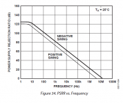
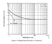
With a 9VAC transformer and a bridge rectifier made from four 3A, 100V Schottky diodes, it appears to me quite straightforward to implement a Jung-Didden "Super Regulator" with all thru-hole components. I'd suggest the 30 year old, ultra low noise OP27 opamp in the DIP-8 package. It's been in production for decades, it is manufactured and sold by more than one semiconductor company, its minimum operating supply voltage is compatible with this set of requirements, it has excellent supply rejection (image 1), and it has ultra-low noise as requested (image 2).
The only circuit change is to undo the supply bootstrap. Instead, power the opamp from a filtered version of the input. RCRC ladder with R=47 and C=1000uF (25V).
I'd also increase the filtration between the VREF generator and the opamp's VIN+ pin, perhaps also using Walt Jung's excellent GLED431 (LINK) as the VREF.
Ultra low noise, easily obtainable components, proven design, thru hole construction, what's not to like?
_
Attachments
To make your life easier, may I suggest you select three? 1. The best embodiment of your original 1 transistor design 2. The best embodiment of the 2 transistor Diego Nonoizer and then 3. the total prizewinner with IR led and whathaveyounot. Thanks again for this great building block.I agree: this thread has grown into a huge, unmanageable behemoth and although there are lots of gems scattered here and there, by Diego, Trileru et al., finding them is a painful chore.
I'll try to create an index of some sort, to ease the task of quickly finding what is needed.
Wish me "bon courage" for this, because it won't be any mean, easy task
With this design you should be able to build any of the versions discussed in the Denoisator thread:
https://www.diyaudio.com/community/...-317-based-v-reg.331491/page-124#post-7090788
The noisefloor, on noise density scale, sat around 220pV/sqrtHz for my discrete design, and a bit higher for LM3x7/LM338. I think around 330pV/sqrtHz (without the LNA+ADC noise). In audio band it comes out at around 45nV total.
PSRR is ~150dB, especially with the NoNoiser.
For questions about part values for needed Vout post on the Denoisator thread.
That is an old design. Boards changed along the way and I decided to drop AC to DC from the board. If you really need the low noise I wouldn't put AC power too close to the regulator.This one includes everything:
https://www.diyaudio.com/community/...grade-any-317-based-v-reg.331491/post-6364045
The posts above have other versions, heatsink placed differently, single side board, etc.
For most applications I'd use the simple Denoisator + IR LED CCS version.
Agreed, the transformer, rectifier and filter cap should ideally be located far enough from the ultra low noise regulator, but it was an OP's request (or was it Jean-Paul?).
Is there a feature for this? Would be great to have a sort of contents sheet where we could update with recommended posts, latest design etcI agree: this thread has grown into a huge, unmanageable behemoth and although there are lots of gems scattered here and there, by Diego, Trileru et al., finding them is a painful chore.
I'll try to create an index of some sort, to ease the task of quickly finding what is needed.
Wish me "bon courage" for this, because it won't be any mean, easy task
Normally, the first post of a thread can be edited by his author; in this case, it will be yours truly, but all suggestions are welcome, especially yours since you have heavily contributed to the thread (moderators can of course also include additions, but they have many other tasks to complete, and if someone else can do it, that's the normal way to proceed).
An alternate solution would be the creation of a new thread, like "A denoiser's guide", but I fear it will end up as cluttered as the original thread.
The two solutions are not mutually exclusive, and you could perfectly open this "guide": you will be the owner and will be able to edit the opening post.
Personally, I am going to create the index in the first post of the denoiser thread, but feel free to create another, parallel thread (and YOU will have to manage it, obviously)
Sorry Bjornmagnus for the threadjacking, but it will be over soon, and in the meantime you have another possible solution to consider
Whether OP or I want it: there is no final working design with PCB for AC to DC purposes (as usually required) suitable for the average DIYer that just wants to build a good PSU. Sorry but it is what it is.
May I suggest to indeed keep all the LM317 designs in their own thread!?
May I suggest to indeed keep all the LM317 designs in their own thread!?
Last edited:
- Home
- Amplifiers
- Power Supplies
- Ultra-Low noise linear power supply 5VDC/0.7A