My other one has a 300 volt supply and I found out the expensive way that tube pins are numbered viewing them from the bottom. I blew up my scope because my input was actually the output.
Evan , the super-pair with EF3 BJT's could be unstable - Val used a EF2 FET
arrangement.
My original Kypton V had issues except with large Cdom around the super-pair
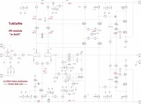
stage. The same IPS without the baxandall was fine. CFA baxandall IPS
was also fine with the EF3.
I think both Thimios and Terry had these issues. 😱
Your bias should be 10ma centered trimmer @ 5.2ma VAS I (all 4 of mine were).
OS
Yes, Pete - this makes a lot of sense. Both EF2 HEX-FET and Lateral-FET direct-drive are fine, but EF3 introduces additional pole that can "change the picture", plus much lower input capacitance...
Yes, Pete - this makes a lot of sense. Both EF2 HEX-FET and Lateral-FET direct-drive are fine, but EF3 introduces additional pole that can "change the picture", plus much lower input capacitance...
Not an issue with your IPS 🙂 , Val .... but with my EF3.
Guru E. Stuart and keentoken informed me of "lack of Ccb" with my "V" and
E. stuarts "TIS".
At this point I could of added the extra driver comp. to my EF3. I did not ,
and changed the IPS to be compatible with the present OPS.
Most IPS's have plenty of Ccb natively and will "get along" with the EF3.
The same Baxandall on my CFA has a larger Cdom and a simple low Z
feedback network - VERY stable w/ the EF3.
Edit - CFA Baxandall has much lower CLG , as well.
OS
Last edited:
I've replaced the LEDs and retested. Voltage on the input is gone. My problem input board is just about perfect. PD - ND voltage is 2.2 volts across 100 ohm resistors with 120 ohms for R29. If I move R29 up to 150 ohms voltage drops to 1.75 volts. Is it better to be higher or lower?
The input board that I thought was good is showing 100mV offset on the output and 1.8 across PD-ND with 120 ohm R28.
The input board that I thought was good is showing 100mV offset on the output and 1.8 across PD-ND with 120 ohm R28.
I've replaced the LEDs and retested. Voltage on the input is gone. My problem input board is just about perfect. PD - ND voltage is 2.2 volts across 100 ohm resistors with 120 ohms for R29. If I move R29 up to 150 ohms voltage drops to 1.75 volts. Is it better to be higher or lower?
The input board that I thought was good is showing 100mV offset on the output and 1.8 across PD-ND with 120 ohm R28.
Ok, good. 1.75V across two 100R resistors give us 8.75mA - about perfect. That's what I use in my build, R29 = 150R. So, better leave 150 there.
The other board seems to have some issue - in normal situation, the circuit auto-balances down to some millivolts offset at the output...
Can you please measure the voltage at the output of the DC servo op-amp (pin 6) - for the good one and the one with the offset. You can also try to swap the tubes for a minute. And also try to rotate R8 and see if there is some reaction with regards to the offset.
I've swapped tubes already. No effect. I measured voltage at pin 3 and 2. 2 dropped right off and drove the offset up. I resweated all the solder joint in the area and retested. Down to 70 mV offset now. I'll check pin 6 and R8.
On the good board pin 6 reads -13.7V. On the defective one it reads +7.42. Adjusting R8 is temporary. The servo cancels the adjustment within a second. Voltage was perfectly balanced between R5 and R10 with R8 centred. Seems to me like the servo itself is holding it off.
The servo is non-inverting, so if there is some small minus at the amp output, it has to be even more minus at the servo output (pin 6). Try to reduce R19 to, say, 22K, and check that the servo works this way.
I let everything run for a while, then checked both channels again. The good channel drifted to -1 volt. I've replaced the tubes with Tung-sol tubes and I'm warming it up again.
Does R29 affect the gain? Will running different values there between channels effect operation?
The voltage at the pin 6 of the servo should never reach +/- 14V (maximum op-amp output voltage). If it does - reduce R19.
Does R29 affect the gain? Will running different values there between channels effect operation?
No, it does not affect the gain. It only affects the VAS current, which is good to have equal for both channels.
I assume that voltage drops over D3, D7 are all the same in both channels. Then voltage drop over R29 is also expected to be the same. Then the same R29 value will set the same bias, resulting in equal VAS current...
The question then - where is the difference?
The question then - where is the difference?
I assume that voltage drops over D3, D7 are all the same in both channels. Then voltage drop over R29 is also expected to be the same. Then the same R29 value will set the same bias, resulting in equal VAS current...
The question then - where is the difference?
Voltage drop is exactly the same on all 4 diodes. I'm thinking the difference is likely whatever is causing my DC offset. I'm going to parallel another 47k resistor on R19 and see what happens. Pin 6 is still positive with negative DC offset.
If pin 6 is positive with negative DC offset - servo works incorrectly. Either op-amp itself or some resistors around it are wrong... It should only amplify the offset (either positive or negative), but should not change the polarity.
I always get crossed up figuring out inverting input and no inverting in operation. Right now with the R19 paralleled wit two 47K resistors I have +.93 volts on pin 2, +.96 volts on pin 3 and +1.93 volts on pin 6. The output is rolling around -30mV.
Well, looks acceptable, although I've got <5mV. Anyway, time to run some sine / square waves through it with the scope attached 😉
That's what I was doing while it was warming up. It plays perfectly. Just a little low on VAS current and a little high on offset.
- Home
- Amplifiers
- Solid State
- Ultra-high performance, yet rather simple - hybrid and more!