OK, this one deserves a separate thread, I believe.
It incorporates a lot of experience gained during the last year or so with simulations, prototypes, measurements, listening, etc.
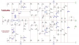
Though, this one is not prototyped yet (working on PCB), it is based on my initial tube hybrid design >HERE< with certain refinements, utilizes a recently developed "super-Hawksford" VAS (inspiration and co-operation from Ostripper ), driving two pairs of lateral MOSFETs directly (already ordered ones for prototype).
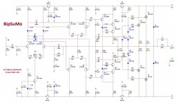
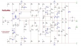
For those, who doesn't want to deal with tubes (athough, I recommend to do so 😛 - takes only additional 6.3VAC source and additional 20 seconds delay at soft-start), I have added a number of IPS LTP options - jFET, BJT and combination of BJT + jFET source follower (note some adjustments in compensation, degeneration and load resistors values). Overall measurements are pretty close, however the tube one shows the best open loop linearity and transients handling (showing the lowest voltage gain at the same time), so my first prototype will go with the tube at the input.
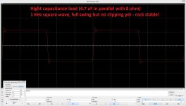
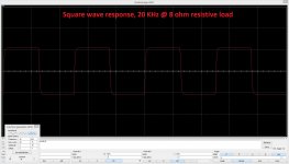
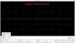
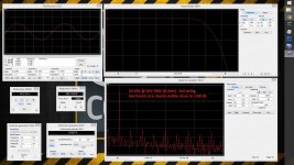
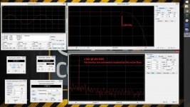
All the virtual measurements shown are also done based on the TubSuMo model. One can say - it's just a model, let's see what real life will show. Agree, but having a lot of experience with modelling and further live prototyping, I would say - this model shows an outstanding, very "clean" performance in many aspects. Even at the swing close to the rails, even with heavy capacitive load, at clipping, etc. It's a hell of a VFA!
I will probably add a DC servo to the final design.
Also thinking about reserving the places for presented IPS options on PCB, so that it can be used for any of them.
It will be possible to use the front-end part in combination with well-known SlewMaster series of OPSs as well.
Stay tuned! 😉
Cheers,
Valery
It incorporates a lot of experience gained during the last year or so with simulations, prototypes, measurements, listening, etc.
Though, this one is not prototyped yet (working on PCB), it is based on my initial tube hybrid design >HERE< with certain refinements, utilizes a recently developed "super-Hawksford" VAS (inspiration and co-operation from Ostripper
), driving two pairs of lateral MOSFETs directly (already ordered ones for prototype).For those, who doesn't want to deal with tubes (athough, I recommend to do so 😛 - takes only additional 6.3VAC source and additional 20 seconds delay at soft-start), I have added a number of IPS LTP options - jFET, BJT and combination of BJT + jFET source follower (note some adjustments in compensation, degeneration and load resistors values). Overall measurements are pretty close, however the tube one shows the best open loop linearity and transients handling (showing the lowest voltage gain at the same time), so my first prototype will go with the tube at the input.
All the virtual measurements shown are also done based on the TubSuMo model. One can say - it's just a model, let's see what real life will show. Agree, but having a lot of experience with modelling and further live prototyping, I would say - this model shows an outstanding, very "clean" performance in many aspects. Even at the swing close to the rails, even with heavy capacitive load, at clipping, etc. It's a hell of a VFA!
I will probably add a DC servo to the final design.
Also thinking about reserving the places for presented IPS options on PCB, so that it can be used for any of them.
It will be possible to use the front-end part in combination with well-known SlewMaster series of OPSs as well.
Stay tuned! 😉
Cheers,
Valery
Attachments
-
 #01-TubSuMo-sch.JPG290.6 KB · Views: 12,832
 -
 @Measurements-08.JPG296.9 KB · Views: 2,029
 -
 @Measurements-05.JPG278.6 KB · Views: 1,388
 -
 @Measurements-02.JPG266.5 KB · Views: 1,485
 -
 @03-Measurements-07.JPG558.5 KB · Views: 1,568
 -
 @02-Measurements-06.JPG548.7 KB · Views: 1,831
 -
 @01-Measurements-01.JPG534.1 KB · Views: 9,768
 -
 #04-ComSuMo-sch.JPG291.3 KB · Views: 10,276
 -
 #03-BipSuMo-sch.JPG282.4 KB · Views: 10,599
 -
 #02-FetSuMo-sch.JPG285.2 KB · Views: 12,265
Member
Joined 2009
Paid Member
Looks good! - I suggest more rail capacitance after the capacitance multipliers, schemo shows only low values.
Thank you Gareth, you're right - these are actually from the sim - it runs simulation in 1/10-th of the real time, so they charge rather slowly there 🙂
Real build values will be higher, I will also add some more caps - will publish here soon.
Real build values will be higher, I will also add some more caps - will publish here soon.
I've been wanting to experiment with these output devices but I'm not having any luck finding them from a reputable supplier in North America.
I've been wanting to experiment with these output devices but I'm not having any luck finding them from a reputable supplier in North America.
I'm surprised Mouser doesn't have them in stock... I've found a local supplier, but it was not that easy 😕
I can't see voltage rails ......
Hi Alex, these are originally designed for +/-70V DC, however any option except the tube one can be easily adapted to the lower voltage...
Super interesting way to "fold" the LTP input into a parallel symmetric 2. stage
very good thinking
very good thinking
OK, this one deserves a separate thread, I believe.
It incorporates a lot of experience gained during the last year or so with simulations, prototypes, measurements, listening, etc.
Though, this one is not prototyped yet (working on PCB), it is based on my initial tube hybrid design >HERE< with certain refinements, utilizes a recently developed "super-Hawksford" VAS (inspiration and co-operation from Ostripper
For those, who doesn't want to deal with tubes (athough, I recommend to do so 😛 - takes only additional 6.3VAC source and additional 20 seconds delay at soft-start), I have added a number of IPS LTP options - jFET, BJT and combination of BJT + jFET source follower (note some adjustments in compensation, degeneration and load resistors values). Overall measurements are pretty close, however the tube one shows the best open loop linearity and transients handling (showing the lowest voltage gain at the same time), so my first prototype will go with the tube at the input.
All the virtual measurements shown are also done based on the TubSuMo model. One can say - it's just a model, let's see what real life will show. Agree, but having a lot of experience with modelling and further live prototyping, I would say - this model shows an outstanding, very "clean" performance in many aspects. Even at the swing close to the rails, even with heavy capacitive load, at clipping, etc. It's a hell of a VFA!
I will probably add a DC servo to the final design.
Also thinking about reserving the places for presented IPS options on PCB, so that it can be used for any of them.
It will be possible to use the front-end part in combination with well-known SlewMaster series of OPSs as well.
Stay tuned! 😉
Cheers,
Valery
Driving those Lateral capacitances directly with the high-Z cascode - abusive. 😀
OS
Driving those Lateral capacitances directly with the high-Z cascode - abusive. 😀
OS
I know 😀
However, sometimes a little bit of abuse does not harm 😉
What I really like - it does not add additional "parasitic" pole to the system (at least not in the "critical" area - close the UGLF).
In some cases, difference in n-MOS and p-MOS input capacitance influences stability, but this can be cured by either adding additional cap or adjusting the gate stopper on one side...
Super interesting way to "fold" the LTP input into a parallel symmetric 2. stage
very good thinking
Very elegant, almost sexy!
/Anders
vzaichenko
That is very promissing design (sansui like). Some time ago I have created a similar amp and it sounded very, very nice, didn't have enough time to fine tune it soundvise but on the paper all looked ok .
I tryed configuration with 4 differential LTP stages (apex HD series amps) and it was stunning but I had lack of knowledge how to sort out bad clipping at higher frequencies (output was sticking a bit). THD figures were also good, all harmonics were 100dB bellow main signal (according to my soundcard).
I am just wondering if it is good to drive output stage directly from cascoded VAS, one time I have putted 2 pairs of IRFP240/9240 mosfets just in front of the VAS cascode and I wasn't satysfied with sound and measurements either (or maybe I was doing something wrong)
Bellow my old schematic.
Attachments
Last edited:
vzaichenko
That is very promissing design (sansui like). Some time ago I have created a similar amp and it sounded very, very nice, didn't have enough time to fine tune it soundvise but on the paper all looked ok .
I tryed configuration with 4 differential LTP stages (apex HD series amps) and it was stunning but I had lack of knowledge how to sort out bad clipping at higher frequencies (output was sticking a bit). THD figures were also good.
I am just wondering if it is good to drive output stage directly from cascoded VAS, one time I have putted 2 pairs of IRFP240/9240 mosfets just in front of the VAS cascode and I wasn't satysfied with sound and measurements either (or maybe I was doing something wrong)
Bellow my old schematic.
Boris, thanx for sharing - this is very close in principle, with some important specialties though 🙂
IRFPs are HEX FET (verticals) - they definitely need a driver (like EF) in front of them. 2SK1058/2SJ162 are laterals - more linear and less capacitance. Although, driving them from a high-impedance cascode collectors is a bit of an abuse (as OS just mentioned 😛), I saw a number of designs where they work very well this way. I'm running VAS at 7mA, which should be is enough for a good result. We'll see on a prototype anyway - I will try a number of options for OPS, including the one with the verticals-through-EF 😉
John Laurence Linsley-Hood drives two pairs of laterals directly from VAS in his 80 W MOSFET amp. The VAS runs at a bit higher current, 10 mA, then yours, and it sounds quite good.
John Laurence Linsley-Hood drives two pairs of laterals directly from VAS in his 80 W MOSFET amp. The VAS runs at a bit higher current, 10 mA, then yours, and it sounds quite good.
Hi Damir, yes, another good example is the design from Rod Eliott, where he feeds 2 pairs of lat-fets from a simple one-transistor VAS, running at 5 mA, with excellent overall performance.
So, most of successful designs, driving lat-fets directly, have VAS current in the range 5-15mA. In case of the lower value, some additional n-channel / p-channel input time constant alignment may be required (either additional cap or slightly higher gate stopper for n-channel), though with higher current lat-fets run fine as is.
I will play with VAS quiescent current value of the prototype, although simulation does not show any issues at 7 mA 😉


- Home
- Amplifiers
- Solid State
- Ultra-high performance, yet rather simple - hybrid and more!