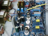
Thomas, here is a pic of my v2 Dac on a temporary chassis. I have used 1 red and 1 brown pair of primary wires for all 3 transformers as you suggest. I have not test yet. Here are my remaining Qs:
1. I am using 6amp on/off switch and 3amp fuse. Is this OK?
2. Planning to use an all-wood chassis (no metal). I have connected all three black wires from each 3 transformers to Earth Ground Point. Also, a green ground wire from IEC is also connected to this same point (brass bolt with brass washer and nut). Is this OK?
3. On the dac pcb, there are two copper clad through-holes marked "Ground". One in the center of the board, and one near the left corner of power supply area. What is the difference between these two? Is one the AC ground of the psu section, and the other the signal ground?
4. On the dac board, there are very small copper through holes NEXT to each of the corner mounting holes. My brass bolts that mount dac board to wood chassis TOUCH these small copper through-holes. For wood chassis, is this OK?
5. On the tube pcb, there is only one copper clad through-hole for Ground. To ground the tube board, do I run a wire from this ground pad to star ground in #2 above?
6. Are their resistors built into the design of both dac and tube board that DRAIN boards when power is turned off, so one can safely touch the components after unplugging dac?
Attachments
And now for something completely different
This V2 tubeboard being my first tube expierence I wanted to extend this expierence to its limits.
Therefor I have talked to some expierenced Tube builders and one came up with a very nice modification for the 6c45pi part.
I did not particular like this tube and therefor asked him if there are posibility's for this circuit.
He (Peter van Willenswaart) came up with the following modification.
His advise was to use the EC81 (NOT the ECC81)!!!! instead of the 6c45pi.
To be able to use this tube you need to make the folowing modification:
1- Replace R41, R53 with 560 Ohm 2W resistors.
2- Connect Anode (pin 7 on the 6c45pi) to pin 8. easy change make a wire bridge between 7 and 8, because 7 is not used on the ec81.
3- Remove R40 and R47 from the pcb and connect it directly to pin 1 of the EC81. It is nesecary to make the lead between the resistors and the pins <1cm therefor connect it directly to the pin of the tube holder. For R40 this is easy because you can solder the other side directly to R7. For r47 one you need to extend the lead with a wire and solder the extention in the same hole as r47 was before.
4- The last thing you have to do is remove the old wires to pin 1(used to be part of the Kathode of the 6c45pi). on both sides of the pcb!!!!!
5- On U6 make a bridge from the little hole (between pin 1 and 9) to pin 3 (or pin9 which is closer).
Thats all folks. 2 new tubes (EC81) and 2 resistors (560 Ohm 2 W) and you got something very nice.
The beauty of this is the ec81 is a lot cheaper then the ECC88 to get the same performance.
Peter also advised me to put a resistor in the heater circuit for the ec81 to extend the livespan. But I know there are different opinions about this. But I have done it and this is how I done it.
1- Remove the line to pin 4, but make sure you do not cut the line towards the other heater pins of the other tubes ("main" heater line).
2- on the "main" heater lines there are through pcb holes now connect a 2R2 1W resistor between these little holes and pin 4 of the tube holders.
Any resistor between 2 and 3 Ohm is OK.
Again that's it.
You are free to use this mod or not. Like I said I did not like the 6c45pi tube and wanted to experiment with tubes, that is why I have done it.
Maybe you have the same reason that is why I posted it
Please do not start to ask Thomas about this change because he had no information about this.
Happy building and most off all Listening.
JeroenVl, congratulations on your mods to the tube stage. Can you describe the sonic differences between the two tube stages: the 6c45 vs. EC81? Did you first build the Dac using the 6c45 stage, or are you dissatisfied with 6c45 in general terms (perhaps having listened to other equipment)? Did you try the 6dj8?
Any feedback on these voltage readings on the secondary windings (not connected to pcb terminals)?
9V secondary = 11.3 V reading
6.3V secondary = 7.7 V reading
230V secondary = 513 V reading
18V secondary = 43.8 V reading
For both the 230V and 18V readings, my meter leads were connected to the 2 AC wires, not the CT lead.
Using 120V here in the USA. Have only 1 red and 1 brown primary lead connected to AC mains.
I understand that the readings should be higher under "no load" conditions, but the 230V and 18V readings seem very high.
Any feedback?
Mike,
I think your voltage readings are ok. If you look on the top of the transformers you will see:
230 - 0 - 230 this means when you measure between the two AC wires you end with 480VAC. So 513VAC should not be a problem.
The same goes for the 18VAC (2*18 = 36VAC).
Like you said you measure without a load.
On the EC81 mod, my advise to you is to get your dac up and running before doing a mod like I suggested. Give yourself sometime to get used to the sound/music it plays.
In regards to the 6C45pi tube. It has been sometime since I last used this tube. It was the first I had in there and I remember I found the Opamps sounded way better then the 6c45pi.
But after I placed a 6922 tube in it I never pulled that one out again. By far the most detail and soundstage of the things I started this project with.
This would be my prefered list:
- Sovtek 6c45pi: Did not like this one. Removed it after listening to the opamps (plus minus one weeks listening).
- OPA627: More detail then the 6C45pi and sounded more natural.
- AD797: Personally liked this one better then OPA627. Why don't know, just sounded nicer in my ears.
- Electro Harmonix 6922. Overclassed everything I listened to before. A lot more detail and soundstage and more natural. Used it for a couple off months.
- Valvo ECC88 goldpins (NOS). More detail then the electro Harmonics. Overal better sounding
- EC81 goldpins (I think Adzam philips made). A lot more detail and soundstage then the 6922. very musical tube.
I have not tried the Philips ECC88 SQ goldpins and the svetlana 6N1P. So I cannot say anything about these yet.
Happy listening
Jeroen
The higher voltage you have is because of 120v supply. My main concern is the supply voltage for the heater of the rectifier tube. You'd better try to reduce it to 6.3v to maintain long tube life. This can be done by connnecting a power resistor in series. Need trial and error here to find the correct value.
Regarding tubes used I have tried the following ECC88
Valvo
Philips Holland
Amperex US gold pin
Buggle boy Holland
The philips holland ones are the best among these. This DAC will show it potential when fitted with higher quality parts.
I have also tried NOS 6N1P-EV made in the sixties by the former soviet union. They are very quiet tube but far behind the philips ECC88 in terms of musicality.
quantran said:you'd better try to reduce it to 6.3v to maintain long tube life. This can be done by connnecting a power resistor in series. Need trial and error here to find the correct value.
no need for trial and error. once you have connected the secondary to the tube's heater, measure the voltage. Get the current draw from the tube's datasheet.
Then you can use ohm's law to measure required resistor. I've seen people use 6V and is still within the heater's tolerance.
Yes, jarthel. You are right.
Actually I don't need to this because my power supply system is about 100v. I riotubes has 120v supply and he got 7.7v for the heater of the rectifier. I think it's very high.
Actually I don't need to this because my power supply system is about 100v. I riotubes has 120v supply and he got 7.7v for the heater of the rectifier. I think it's very high.
riotubes said:Any feedback on these voltage readings on the secondary windings (not connected to pcb terminals)?
9V secondary = 11.3 V reading
6.3V secondary = 7.7 V readingAny feedback?
you can try measuring the secondary voltages at different times. AC from the wall socket can vary throughout the day and you may have measured it when it was high.
Thanks for all the feedback
Plugged it in. Nothing but low-frequency, chaotic "garble" sound.
Although I plan to re-measure the 6.3V reading, I wanted to see if the Dac would play music. I hooked it up, and initially no sound. no hum. nothing. After turning power off, I flicked the toggle switches on the tube board in the opposite direction (I'm using 6c45 tubes, not the 6dj8). I then heard chaotic, low frequency "garble". I don't know how else to describe it. No hum or buzz. No music. Like someone crinkling a piece of paper, but lower frequency only. I immediately powered down.
Can you help me diagnose? Here are some relevant facts:
Pic of dac is in post #581 above. Dac installed on temporary plywood chassis. The iec ground wire runs to single point ground where 3 black leads from each transformer are also connected to a brass bolt by the transformers. I tightly twisted each secondary, and connected them to the appropriate terminals. I received excellent feedback from Quan Tran on where to install each lead.
1. The voltage readings for all secondary trans are in post #584 above.
2. The tube board came pre-assembled by Thomas
3. Op-amp output pcb is not installed.
4. I soldered small copper jumper in both J2 and J3 on tube board
5. Using Audio Consulting silver wire (twisted pair) for all analog cable.
6. Using VHAudio pulsar mini-coax for digital wire. Center coax conductor soldered to SK5 pin closest to input transformer. metal braid of coax soldered to SK5 pin closest to psu.
7. Thomas supplied dario miniwatt EZ80 rectifier tube. 6X4 socket is empty (no tube).
8. I ordered 2 6C45 tubes from Thomas extra. The tubes I received are unmarked. I assume they are 6c45. How would I tell if they are indeed 6c45 and not 6dj8 by mistake? 6dj8 sockes are empty (no tubes).
9. Dac is plugged into balanced power conditioner.
10. My CDP (Ah Tjoeb) has Digital Out. Using this as transport.
11. Using DIY Belden 1505a cable for IC (Thomas supplied this cable with kit). Canare BNC on Dac end, Canare RCA on Transport end.
12. Dac analog out (VH Pulsar shielded ICs) goes to S&B TVC passive preamp, then to 300B monos.
Is it safe to deduce this is a signal problem, and not a psu problem?
Any thoughts? javascript:smilie(' ')
')
smash
Plugged it in. Nothing but low-frequency, chaotic "garble" sound.
Although I plan to re-measure the 6.3V reading, I wanted to see if the Dac would play music. I hooked it up, and initially no sound. no hum. nothing. After turning power off, I flicked the toggle switches on the tube board in the opposite direction (I'm using 6c45 tubes, not the 6dj8). I then heard chaotic, low frequency "garble". I don't know how else to describe it. No hum or buzz. No music. Like someone crinkling a piece of paper, but lower frequency only. I immediately powered down.
Can you help me diagnose? Here are some relevant facts:
Pic of dac is in post #581 above. Dac installed on temporary plywood chassis. The iec ground wire runs to single point ground where 3 black leads from each transformer are also connected to a brass bolt by the transformers. I tightly twisted each secondary, and connected them to the appropriate terminals. I received excellent feedback from Quan Tran on where to install each lead.
1. The voltage readings for all secondary trans are in post #584 above.
2. The tube board came pre-assembled by Thomas
3. Op-amp output pcb is not installed.
4. I soldered small copper jumper in both J2 and J3 on tube board
5. Using Audio Consulting silver wire (twisted pair) for all analog cable.
6. Using VHAudio pulsar mini-coax for digital wire. Center coax conductor soldered to SK5 pin closest to input transformer. metal braid of coax soldered to SK5 pin closest to psu.
7. Thomas supplied dario miniwatt EZ80 rectifier tube. 6X4 socket is empty (no tube).
8. I ordered 2 6C45 tubes from Thomas extra. The tubes I received are unmarked. I assume they are 6c45. How would I tell if they are indeed 6c45 and not 6dj8 by mistake? 6dj8 sockes are empty (no tubes).
9. Dac is plugged into balanced power conditioner.
10. My CDP (Ah Tjoeb) has Digital Out. Using this as transport.
11. Using DIY Belden 1505a cable for IC (Thomas supplied this cable with kit). Canare BNC on Dac end, Canare RCA on Transport end.
12. Dac analog out (VH Pulsar shielded ICs) goes to S&B TVC passive preamp, then to 300B monos.
Is it safe to deduce this is a signal problem, and not a psu problem?
Any thoughts? javascript:smilie('
')smash
Mike,
Do you have the crackling sound, when:
1- Cd is playing or not.
2- Tube board not connected to the DAC board
Have you checked the wireing to ensure you have not made a short between the + and - on your signal wires.
Also check if the jumpers on Sk7 are on their correct posistion.
Also check if the dipswitches on S1 are on their right position, without reclocking 1,3,5 and 6 should be on the rest off.
Do you have a cope? If yes check if the DAC board is causing this or the tube buffer. Best to use a sinus test signal.
I have looked, but I do not see How to differentiate between a 6C45pi and 6dj8.
Good luck
Did the blue LED on the DAC board light up?
If you are in doubt about the tube type check these pictures
6c45pi http://www.iwdiy.com/ShoppingMall/images/T-Preamp/6C45G-EH-N1.JPG
ecc88 http://www.coherentaudio.com/prodpictures/10366.JPG
The contructions inside are different between these 2 types.
If you are in doubt about the tube type check these pictures
6c45pi http://www.iwdiy.com/ShoppingMall/images/T-Preamp/6C45G-EH-N1.JPG
ecc88 http://www.coherentaudio.com/prodpictures/10366.JPG
The contructions inside are different between these 2 types.
You guys are terrific. Much appreciated.
I am at work, so I will try these diagnostics tonight.
SK7? I have not done anything with SK7. Must I do something?
Quan Tran: I do not have a blue LED, so I did not hook this up to SK8. I will study the tubes tonight.
BTW, I do not have anything hooked up to SK4 either (18v-0-18v). Just SK1.
I will look at the dipswitch to make sure 1, 3, 5 and 6 are "off" (no reclocker installed)
Thank you
Mike,
SK7 connects the CS8414/cs8412 to the TDA1541 chips, there should be 3 jumpers on it. Or the reclocking circuit.
But right now this is not the issue because you should atleast have a bleu led
Sorry my bad: Dipswitches 1, 5 must be ON and the rest Off. (I have the reclock installed and used this as a reverence)
SK4 is DC 18 volts which can be used for the reclocking circuit, but for now just use the jumpers on SK7.
OK. I can pick up a blue led today. What am I looking for? Amp/voltage rating? What kind of wire can I use? Twisted pair? and what guage? thanks
Mike,
I think you misunderstand me, There is (or should be) a blue led on the DAC board (ps it is transparant when not lid).
This led should light up when the cd player is playing (blue light).
What Quantran asked was if this led light on.
Because you wrote it did not, the jumpers on SK7 are not really important right now, because the cs8414/cs8412 are not locked to the signal yet (No Blue led).
I hope this clears things up a little
Tube-lover (Thomas) is On Leave
Dear all,
Just want to let you know that my friend, Tube-lover (Thomas) has been admitted to the hospital for a minor surgery. He will not respond to any enquiries till mid next week.
Regards,
T.C. MA
13 Sep. 2006
Dear all,
Just want to let you know that my friend, Tube-lover (Thomas) has been admitted to the hospital for a minor surgery. He will not respond to any enquiries till mid next week.
Regards,
T.C. MA
13 Sep. 2006
I am sad to hear this news. Thomas, we wish you a successful procedure and a fast recovery!
Best regards,
Mike (RioTubes)
Best regards,
Mike (RioTubes)
Here are my findings based on the suggestions:
I have not power up again because there is no LED installed.
1. There is no LED on the board. If it goes in SK8, SK8 is empty. I'm posting a pic of the only part that remotely resembles a LED. It reads 12V 5W. Is this it, and does it go on SK8? I can't tell if it has a pos and neutral side, I imagine it doesn't matter.
2. DIP switch is good. 1 and 5 are "on". All others "off"
3. SK7 has 3 jumpers installed across 1&2, 3&4, 5&6 pins. I did not touch SK7 so I imagine the jumpers were installed correctly.
4. All + and - signal wire appear correctly installed. No shorts.
5. Tubes. I ordered 6c45. They actually look more like 6DJ8 from Quan Tran's pics. The label has long since worn off, but I can barely make out a few digits ...something that ends in "A8" and then on 2nd line it reads something that ends in "5A4". In the larger pic, you can see there is a ring that extends upward like a halo that the 6c45 does not have. Any ideas?
6. For 6dj8, should toggle switches be turned "in" towards each other or face "out"?
7. SK6 (SYN) is blank. R39 and R47 near dac left & right output are blank.
Attachments
Riotubes,
The photos you posted are definitely 6dj8 (Ecc88). Plug them in the 6DJ8 Socket and try. Hopefully the tubes are still alive because pin configurations of 6dj8 and 6c45pi are different.
For 6dj8, the 2 tube switchs should be pointed inward to each other. I attache a photo of my DAC with ECC88 tubes so you can see.
Attachments
- Status
- Not open for further replies.
- Home
- Vendor's Bazaar
- Ultimate Twin TDA1541a Non-oversampling DAC with tube buffer & reclock set.......