Are this an ultimate approach for an error correction topology for Class B and getting sound like pure Class A at the same time?
This topology from Anders Thule also inside by some amplifiers from Teac (go to the first PDF attachement) as I note today.
In my old folder from Thule Audio there is to read follow:
One topic of key interest is to reduce the switching distortion and output impedance without compromising the time response performance at a complex load. The switching distortion appears when the power output transistors are switching and sounds particular hard and unmusical.
For this reason Thule Audio has developed a special error correction circuit, which convert the power output transistors to an near perfect buffer, to eliminate nearly all switching distortion. The remaining distortion is a more "musical" type.
The damping factor is increased (= low output impedance) to about 80 for unbalanced and about 150 for balanced products and is identical for low and high frequencies, which are very good values.
Therefore the Spirit amplifiers have:
None global feedback for good stability
Reasonable low distortion (THD < 0.08%, 20-20k Hz).
High damping factor, for both high and low frequencies, for good drive capability
This combination has the wanted dynamic, open and detailed sound, which on the other hand never becomes hard.
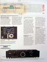
Because I discover this topology also by Teac - thus Anders Thule also developed for Teac
A power amp schematic sample of TEAC A-BX10 you will find in the first PDF attachement and some other images of the devices in follow attachements.
The complete schematic of TEAC A-BX10 you can download there:
ftp://ftp.vegalab.ru/%D1%C5%D0%C2%C8%D1-%CC%C0%CD%D3%C0%CB%DB/TEAC/
The whole circuit topology is close to his own IA-50/IA100 amplifiers
Are this error correction topology really developed from Anders Thule?
Except by Thule and Teac devices I haven't see this topology.
Who knows more?
This topology from Anders Thule also inside by some amplifiers from Teac (go to the first PDF attachement) as I note today.
In my old folder from Thule Audio there is to read follow:
One topic of key interest is to reduce the switching distortion and output impedance without compromising the time response performance at a complex load. The switching distortion appears when the power output transistors are switching and sounds particular hard and unmusical.
For this reason Thule Audio has developed a special error correction circuit, which convert the power output transistors to an near perfect buffer, to eliminate nearly all switching distortion. The remaining distortion is a more "musical" type.
The damping factor is increased (= low output impedance) to about 80 for unbalanced and about 150 for balanced products and is identical for low and high frequencies, which are very good values.
Therefore the Spirit amplifiers have:
None global feedback for good stability
Reasonable low distortion (THD < 0.08%, 20-20k Hz).
High damping factor, for both high and low frequencies, for good drive capability
This combination has the wanted dynamic, open and detailed sound, which on the other hand never becomes hard.
Because I discover this topology also by Teac - thus Anders Thule also developed for Teac
A power amp schematic sample of TEAC A-BX10 you will find in the first PDF attachement and some other images of the devices in follow attachements.
The complete schematic of TEAC A-BX10 you can download there:
ftp://ftp.vegalab.ru/%D1%C5%D0%C2%C8%D1-%CC%C0%CD%D3%C0%CB%DB/TEAC/
The whole circuit topology is close to his own IA-50/IA100 amplifiers
Are this error correction topology really developed from Anders Thule?
Except by Thule and Teac devices I haven't see this topology.
Who knows more?
Attachments
Last edited:
About
http://www.diyaudio.com/forums/solid-state/126352-what-happen-thule-audio.html
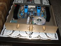
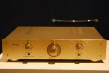
you will find many pictures from a visit in the factory of Thule Audio, that I have found on a Danish website.
http://www.diyaudio.com/forums/solid-state/126352-what-happen-thule-audio.html
you will find many pictures from a visit in the factory of Thule Audio, that I have found on a Danish website.
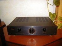
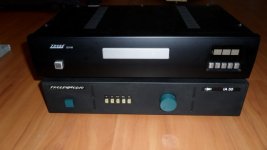
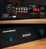
Teac Made in Denmark by Anders Thule
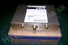
Anders Thule from Thule Audio not only developed for Teac. He even produced for Teac at least the model "ABX-10" from previous post and the A-BX7R (ABX-7R, see pdf attachement)
The A-BX10 ii seems to be close by Thule's model IA-100 (the predecessor of the IA-100 from the "Spirit"-line); and the ABX7R? this I don't know (perhaps the unbalanced and unbridged version of IA-50). Thus I can also offer service for this models and all the other Teac's stereo devices, where Thule Audio components are inside.
Attachments
Last edited:
Thule calls their Error Correction "Virtual Class A"
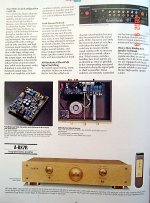
about the Alexis Internet Archive I have found this and have create and attached PDF-Files. The last file is the schematic of Thule Audio's unbal. amp devices with follow PCB: EM1070 Rev 8. Here is to see a current mirror insted a CCM
about the Alexis Internet Archive I have found this and have create and attached PDF-Files. The last file is the schematic of Thule Audio's unbal. amp devices with follow PCB: EM1070 Rev 8. Here is to see a current mirror insted a CCM
Attachments
Last edited:
What am I missing here?
It just looks like ramming some one-sided current into the pre-driver to create some DC off-set (to be corrected by the front-end). I guess this would insure that one half of the output stage doesn't turn off.
OK, but I see 10k R's in series with this "one sided current injection", so whatever it's doing current wise, it's not doing much.
Marketing hype, IMO.
Regards, Allen
What effects you observe by your faulty device? And how old is it?I have the abx-10 and it requires a service. TEAC are very unhelpful and the manual and service manuals are nowhere to be found on the web! Arrgh! They were quick enough to take £1000 off me though.
Burned output stage has biggest probability caused by thermal failure biasing from heated 1st and 2nd stage of tripleEF.
TripleEF should not used for mass production without good professional hand at finishing.
I agree. Thermal failure is one effect. The other is the risc of oscillation by the use of triple emitter follower at certainly loads. Therefore I reduce the output stage from triple Emitter follower (T-Circuit) to a normal darlington design by a wide range of models in such cases.
In this case also this thread could be of interest:
http://www.diyaudio.com/forums/solid-state/155582-help-amp.html
- Status
- This old topic is closed. If you want to reopen this topic, contact a moderator using the "Report Post" button.
- Home
- Amplifiers
- Solid State
- Ultimate ECC for Class B from Thule Audio? Topology also used by Teac