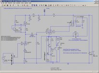
I’ve been working with the single end amp using a 6N1P as input and 6P1P as output (image 1). Input stage has an LED with 100ohm resistor in series (for feedback) for bias. Anode is current source driven. The current source is adjustable for tuning distortion. I’ve been changing feedback in the output stage between UL, GNFB and a combination of the two.
GNFB elicits the response I expect in that it reduces output amplitude, and when the output is re-adjusted to 0.500V I have lower distortion than I had measured without the GNFB.
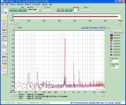
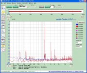
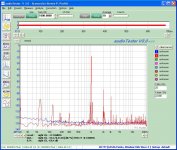
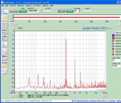
However, I’ve found that when I hook up the UL tap to the screen, the amplitude drops as expected, but when I re-adjust the output to 0.500Vrms the THD (image 3) has gone up above the level seen without UL connections (image 2)!
I can remove the GNFB and get similar results in that UL decreases amplitude (so it is negative feedback) but it increases distortion over what is seen without it at the same signal level.
The transformer is a Edcor XSE10-8-10K. I checked the signal amplitude on the transformer primary and the screen tap signal amplitude is about 40% of the plate connection signal amplitude, so the transformer taps are wired correctly and it is hooked up correctly. I also tried a second transformer with the same results.
Test frequency is 1KHz.
IM seems to go down as seen in the sidelobes of the 1KHz test signal, but overall THD goes up.
GNFB elicits the response I expect in that it reduces output amplitude, and when the output is re-adjusted to 0.500V I have lower distortion than I had measured without the GNFB.
However, I’ve found that when I hook up the UL tap to the screen, the amplitude drops as expected, but when I re-adjust the output to 0.500Vrms the THD (image 3) has gone up above the level seen without UL connections (image 2)!
I can remove the GNFB and get similar results in that UL decreases amplitude (so it is negative feedback) but it increases distortion over what is seen without it at the same signal level.
The transformer is a Edcor XSE10-8-10K. I checked the signal amplitude on the transformer primary and the screen tap signal amplitude is about 40% of the plate connection signal amplitude, so the transformer taps are wired correctly and it is hooked up correctly. I also tried a second transformer with the same results.
Test frequency is 1KHz.
IM seems to go down as seen in the sidelobes of the 1KHz test signal, but overall THD goes up.
Attachments
Last edited:
It looks like UL gives slightly higher 2nd-order and slightly lower 3rd-order. This would probably sound a little better.
I think the reason for this is that the UL connection is reducing the gain slightly more than the open-loop 2nd-order distortion, so the overall 2nd goes up slightly. However, some of the 3rd-order distortion with global feedback is coming from recycling the 2nd-order so dropping the raw 2nd reduces the 3rd, in effect, twice over.
I think the reason for this is that the UL connection is reducing the gain slightly more than the open-loop 2nd-order distortion, so the overall 2nd goes up slightly. However, some of the 3rd-order distortion with global feedback is coming from recycling the 2nd-order so dropping the raw 2nd reduces the 3rd, in effect, twice over.
It's a maybe-not-so-well-known fact that UL and triode modes both have higher distortion than pentode mode with an equal amount of NFB.
The reason: the screen is a nonlinear input with low gain. It also trashes power output because maximum plate current is controlled directly by screen voltage.
If anything, connect the screen to the *opposite* side of the OPT, providing a limited amount of positive feedback. This will greatly enhance the peak current and gain of the tube, allowing more power output for a given supply voltage, while reducing overall distortion because gain is higher. (Note that the screen taps must be fairly low to avoid hysteresis, and the OPT must be constructed well to avoid phase shifts.)
Tim
It is true that the screen is a non-linear input, but it has the advantage that its non-linearity to some extent is the same shape as the control grid's non-linearity.
If you introduce positive feedback in the output stage you have to be careful not to make a power oscillator. If you manage to avoid this, then you may find that the 2nd-order has gone down, the 3rd-order has come up and you will have a rather loud amplifier - which some may prefer. I think you will have traded quality for quantity. Positive feedback within a negative feedback loop can sometimes work, but I would have thought it needs much more loop gain in order to adequately reduce all the recycled higher-order distortion. Some folk will then say that it sounds like a solid-state amp.
If you introduce positive feedback in the output stage you have to be careful not to make a power oscillator. If you manage to avoid this, then you may find that the 2nd-order has gone down, the 3rd-order has come up and you will have a rather loud amplifier - which some may prefer. I think you will have traded quality for quantity. Positive feedback within a negative feedback loop can sometimes work, but I would have thought it needs much more loop gain in order to adequately reduce all the recycled higher-order distortion. Some folk will then say that it sounds like a solid-state amp.
If anything, connect the screen to the *opposite* side of the OPT, providing a limited amount of positive feedback......you will have a rather loud amplifier - which some may prefer
I also found a little drawback to this connection. Play it too loud for too long and the screen grid in your output tubes will MELT leading to fireworks and fried parts. Some tubes can deal with this connection, and some can not. The EL84 can not. Don't ask me how I know this!
Yes, UL requires tubes that tolerate high screen voltages; inverse UL, even moreso. 6L6 is a good candidate; sweep tubes are not!
Tim
Tim
Is this particular to Single ended amps vs PP amps?
I was under the impression that UL would reduce both the pentode output impedance and THD. In the PP version it did reduce distortion.
I'm going to go back and take the measurements over again tonight.
I plan to try Schade as well, but wonder how effective it will be feeding back to the plate of the driver with it being driven from a current source. I'm limited as to how much feedback I can go with before I upset the current source.
In the PP version it did reduce distortion.
Remember, in push-pull, you can increase 2nd to decrease odd orders since the second will cancel out.
Is it possible you really have a mismatched transformer to your tube? 10K hanging from a 5K tube? Isn't the 6P1P = to the 6bq5?
6P1P is probably closer to 6AQ5, but both 6AQ5 and 6BQ5 (along with 6V6 from which they came) are 5K plate load tubes. If Push-Pull, they are 10K, but this is a SE amp.
I found some very interesting results that I will post tomorrow. Now is time for the dogs to get their meds and I need to hit the pad.
I found some very interesting results that I will post tomorrow. Now is time for the dogs to get their meds and I need to hit the pad.
Hello TheGimp,
From looking a couple of your posts it looks like you have found success using Pete Millett’s Test & Measurement interface for Soundcard and Audio Tester. Nice job and nice test plots.
DT
All Just for fun!
From looking a couple of your posts it looks like you have found success using Pete Millett’s Test & Measurement interface for Soundcard and Audio Tester. Nice job and nice test plots.
DT
All Just for fun!
My additional isolation transformers came in yesterday but I didn't have a chance to install them yet as I need power connectors for them. Hopefully I'll get the power related noise down with them.
I ran some more tests on distortion instead.
The output stage is configured as a tetrode with 265V supply (-13V bias = 252Vk-a). Bias is provided by an adjustable voltage sink regulator (TL431 ref with Darlington output). The output transformer is an Edcor XSE10-8-5K 10W SE transformer.
Testing was at 39.5mA anode current (measured with a 10R sense resistor). All tests were made by making the circuit changes, powering up the system, adjusting the bias to insure 39.5mA anode current, adjusting the input for 0.505Vrms (32mW into 8 Ohms) out as measured with an oscilloscope.
This series of tests were prompted when removing the series 1K resistor from the screen connection to the UL tap on the transformer (resistor not seen on a lot of schematics) while expecting to see distortion go down and instead it went up!
No UL:
RS = 1K, THD = 0.9539%
RS = 4K5, THD = 0.454%
UL:
RS = 1K, THD = 1.0313%
RS = 4K5, THD = 0.4154%
UL + GFB (-6.7dB)
RS = 4K5, THD = 0.2140
0.0022uF in parallel with Rfb was determined experimentally to reduce the overshoot and ringing (100KHz) on the leading edge of a 10KHz square wave input. Full voltage swing of over 10Vp-p results in a rise time of <8us. This is actually over-dampened and 0.0015-0.0018uF would probably be a better value but I couldn’t find this value last night.
This gives a full power bandwidth of 19.89Khz. (Fp=S/2 PI Ep) where:
Fp is full power bandwidth
S is slew rate in V/s
Ep is the peak to peak voltage
Observations:
1. Increasing the screen resistor value decreased distortion. Is this because as the screen voltage decreases, the transfer curves are compressed, and become more linear in the process? If so, then simply reducing the screen voltage in Tetrode only mode should accomplish a similar reduction in distortion at the expense of output power.
2. Decreasing THD is seen as reducing 2nd harmonic at the expense of 3rd harmonic, and IM distortion.
These changes are most dramatic when a combination of UL and global feedback are utilized.
I suspect this is why lower THD is not solely a criterion for a good amp. Sound quality is determined by the mix of harmonics AND IM, all of which are measured as one number when taking THD measurements.
I should go back and measure distortion with UL plus global feedback and a 1K screen resistor , and no screen resistor to see if it further reduces IM and 3rd harmonic with an increase in 2nd Harmonic distortion.
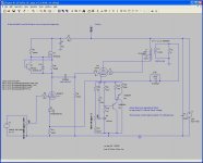
I’ve only posted the UL + GFB RS=4K5 plot but will post the rest (or email them) if someone is interested in comparing them, other wise I won't post them to keep from sucking up space and bandwidth. I've also posted the final schematic, although I may change the screen resistor back to 1K or even eliminate it depending on listening tests. It is sounding pretty good except on some instrumental passages there is a slight fuzz that may be IM related.
I ran some more tests on distortion instead.
The output stage is configured as a tetrode with 265V supply (-13V bias = 252Vk-a). Bias is provided by an adjustable voltage sink regulator (TL431 ref with Darlington output). The output transformer is an Edcor XSE10-8-5K 10W SE transformer.
Testing was at 39.5mA anode current (measured with a 10R sense resistor). All tests were made by making the circuit changes, powering up the system, adjusting the bias to insure 39.5mA anode current, adjusting the input for 0.505Vrms (32mW into 8 Ohms) out as measured with an oscilloscope.
This series of tests were prompted when removing the series 1K resistor from the screen connection to the UL tap on the transformer (resistor not seen on a lot of schematics) while expecting to see distortion go down and instead it went up!
No UL:
RS = 1K, THD = 0.9539%
RS = 4K5, THD = 0.454%
UL:
RS = 1K, THD = 1.0313%
RS = 4K5, THD = 0.4154%
UL + GFB (-6.7dB)
RS = 4K5, THD = 0.2140
0.0022uF in parallel with Rfb was determined experimentally to reduce the overshoot and ringing (100KHz) on the leading edge of a 10KHz square wave input. Full voltage swing of over 10Vp-p results in a rise time of <8us. This is actually over-dampened and 0.0015-0.0018uF would probably be a better value but I couldn’t find this value last night.
This gives a full power bandwidth of 19.89Khz. (Fp=S/2 PI Ep) where:
Fp is full power bandwidth
S is slew rate in V/s
Ep is the peak to peak voltage
Observations:
1. Increasing the screen resistor value decreased distortion. Is this because as the screen voltage decreases, the transfer curves are compressed, and become more linear in the process? If so, then simply reducing the screen voltage in Tetrode only mode should accomplish a similar reduction in distortion at the expense of output power.
2. Decreasing THD is seen as reducing 2nd harmonic at the expense of 3rd harmonic, and IM distortion.
These changes are most dramatic when a combination of UL and global feedback are utilized.
I suspect this is why lower THD is not solely a criterion for a good amp. Sound quality is determined by the mix of harmonics AND IM, all of which are measured as one number when taking THD measurements.
I should go back and measure distortion with UL plus global feedback and a 1K screen resistor , and no screen resistor to see if it further reduces IM and 3rd harmonic with an increase in 2nd Harmonic distortion.
I’ve only posted the UL + GFB RS=4K5 plot but will post the rest (or email them) if someone is interested in comparing them, other wise I won't post them to keep from sucking up space and bandwidth. I've also posted the final schematic, although I may change the screen resistor back to 1K or even eliminate it depending on listening tests. It is sounding pretty good except on some instrumental passages there is a slight fuzz that may be IM related.
Attachments
Last edited:
1K screen resistor resulted in higher THD, but lower IM. The THD increase was mostly 2nd order with 3rd remaining the same. Beyond that it was difficult to see the harmonics.
No screen resistor (Transformer UL tap straight to screen) had the same effect. With no screen resistor, IM was down over 15dB from that seen with the 4K5 screen resistor.
Sound wise, the 4K5 resulted in fuzzy sounding voices and some instruments. Even with -6.7dB gfb.
1Kscreen resistor test was noticeable better than the 4K5 test. However it was difficult to tell the difference between the 1K and no screen resistor. It may be that it would be discernible to a better trained ear.
There was also a slight lowering of the noise floor, but that may be a test to test variation.
60Hz was noticeably down with the lower screen resistor value as well.
Attachments
Hello TheGimp,
You are bringing up some interesting thoughts with your study of the influence of different connections at the screen. The AudioTester screen shots look to be a good tool.
I recall Morgan Jones discussing the screen as a point to inject a percentage of the power supply AC component. We would prefer not to have power supply ripple or other AC but it does. The power supply has an impedance that interacts with the current through the load (speaker) and tube. The affect of input at the screen is 180 degrees out of phase with the grid. The degree of influence that the screen has is a parameter that is not on the cut sheet and can vary from brand to brand of from day of production for an otherwise identical tube. I may be in trouble if I believe everything I read.
Just for grins what happens to the 60, 120 and 180 Hz spikes in the FFA if you add a 10 Henry choke between the capacitors in the power supply? Also what happens to the IMD?
DT
All Just for fun!
Are you sure? The screen, as a grid, has a similar effect to the control grid although lower gain and much lower impedance. The effect of changing screen voltage is shown in some data sheets. The degree of influence is summarised in the g2-g1 mu, which is often given for pentodes.The affect of input at the screen is 180 degrees out of phase with the grid.
I picked up a 8.8H choke yesterday at the local electornics store for $5 (they have a shelf of used parts/equipment on consignment) so I can try a choke in the PS to see how it effects the output, but since this is an SE amp, I expect it to reduce the 120Hz component and it's harmonics. The choke passed HI-POT at 4500V so it should be safe.
Unfortunatly, I've found very little screen characteristic curve data for 6P1P/E/EV.
Unfortunatly, I've found very little screen characteristic curve data for 6P1P/E/EV.
Hello DF96.
100% sure no. 91% yes. Injecting Power Supply voltage at the screen to reduce noise at the output is a technique discussed by Morgan Jones and looks to worth testing. Tying G2 to G1 reduces the voltage to G2 and changes G2 role from plate like to control grid. When G2 is tied to B+ it acts more as a secondary plate, positive voltage as opposed to negative voltage on G1 this explains the out of phase nature of things. This is good stuff to test with TheGimp’s test gear (mine is not complete yet).
DT
All just for fun!
- Status
- Not open for further replies.
- Home
- Amplifiers
- Tubes / Valves
- UL Connection results in higher distortion