Yves Smolders said:
How about a relay in parallel over your existing softstart (if you have one 😀 ) - and use it to ground the /on signal?
A switch can still be added...
That's what I was thinking, but i haven't my transformer/softstart yet.
Oh, and how can I easily add a to see if my amps are on?
Yves
Yep that could work OK.
How can you add.... an LED?
/ON--------------------------------------
Positive rail------/\/\/\/-------->| ----------(switch)------Ground
Edit: Yeah ok that's supposed to look like the /ON connects between the LED and switch
classd4sure said:
Yep that could work OK.
How can you add.... an LED?
/ON--------------------------------------
Positive rail------/\/\/\/-------->| ----------(switch)------Ground
Edit: Yeah ok that's supposed to look like the /ON connects between the LED and switch
I would remove the LED that is on the UcD module, put two wires in place and on the other end of the wires you put the led that goes to the front panel of your amp. This gives you direct feedback what the UcD is doing. Also, Jan-Peter said somewhere in some of the threads that it was OK to do this.
Gertjan
ghemink said:
I would remove the LED that is on the UcD module, put two wires in place and on the other end of the wires you put the led that goes to the front panel of your amp. This gives you direct feedback what the UcD is doing. Also, Jan-Peter said somewhere in some of the threads that it was OK to do this.
Gertjan
It seems some people dont' have LED's on their modules.
The first batch of 400 modules did not have a LED onboard. The new ones have and so does all the 180.
Koldby
Koldby
I'm wondering how many different version of the UcD180/400 have been shipped, and whether there are any physical differences? The pictures as featured on Hypex' website are from prototypes as far as I can tell as the actual modules look a bit different. Anybody care to snap a few shots of a recently purchased UcD180/400 and an older one, both top and bottom and post those here?
Best regards,
Sander Sassen
http://www.hardwareanalysis.com
Best regards,
Sander Sassen
http://www.hardwareanalysis.com
The current pictures on the website are the production modules we sell now.
There are less changes as you suggest. We have add overvoltage protection to both models and changed in the UcD400 from JST connectors to Faston, and the UcD400 has a new coil with higher output current capability.
The physical size are all the same!
Regards,
Jan-Peter
There are less changes as you suggest. We have add overvoltage protection to both models and changed in the UcD400 from JST connectors to Faston, and the UcD400 has a new coil with higher output current capability.
The physical size are all the same!
Regards,
Jan-Peter
Thanks Jan-Peter,
How about a few shots of currently shipping modules in a bit higher resolution than those in the pdf files found on the Hypex website? I'd like to know what I buy and what components are used on them before I start to order.
Best regards,
Sander Sassen
http://www.hardwareanalysis.com
Ps. Jan-Peter, even ter informatie, ons subwoofer artikel wordt binnenkort geplaatst, daarbij maken we uiteraard ook gebruik van de HY-200 module die Hypex ter beschikking heeft gesteld.
How about a few shots of currently shipping modules in a bit higher resolution than those in the pdf files found on the Hypex website? I'd like to know what I buy and what components are used on them
??????, we use all SMD so what do you like to recognize???
On the website is a good detailed picture of theAD8620.
Jan-Peter
SSassen said:Anybody care to snap a few shots of a recently purchased UcD180/400 and an older one, both top and bottom and post those here?
I think there have been some minor production changes since I took these photos. Click on any of them for a larger rendition.
UcD photos
Cheers, mac.
@Mac,
I think your UcD400 are "old" versions.
Mine (later serial numbers) are the 1.1 versions, and have speaker/power connectors like the UcD180 in your pictures
BTW, there's a slash missing in your URL.
Yves
I think your UcD400 are "old" versions.
Mine (later serial numbers) are the 1.1 versions, and have speaker/power connectors like the UcD180 in your pictures
BTW, there's a slash missing in your URL.
Yves
Thanks mac,
You forgot to add a forward slash to that url though, it should read like this.
http://cornucopia.sytes.net/~mike/ucd/
Best regards,
Sander Sassen
http://www.hardwareanalysis.com
You forgot to add a forward slash to that url though, it should read like this.
http://cornucopia.sytes.net/~mike/ucd/
Best regards,
Sander Sassen
http://www.hardwareanalysis.com
this may have come up already but i couldn't find it searching this thread sooo... here i go.
In the datasheet there are fuses in the v+ and v- rails (after rectification), specified at 8A fast. What happens if one of these fuses blows?
In the datasheet there are fuses in the v+ and v- rails (after rectification), specified at 8A fast. What happens if one of these fuses blows?
In the datasheet there are fuses in the v+ and v- rails (after rectification), specified at 8A fast. What happens if one of these fuses blows?
Good question, my guess would be the module stops working. The module has got an overvoltage protection, but if one fuse fails then one power rail is not present, this is something entirely different. I doubt it will work normally as both the positive and negative rail are needed to make it work.
The real question is whether it is engineered so that the absence of either power rail causes it to not output anything to the speaker terminals and mute the input. Otherwise you'll end up with loud popping speaker cones, and that's usually a one off event.
But I guess Jan-Peter will know the answer to this question, are their any fail safe mechanisms built in for the above raised scenario?
Best regards,
Sander Sassen
http://www.hardwareanalysis.com
Yves Smolders said:@Mac,
I think your UcD400 are "old" versions.
Mine (later serial numbers) are the 1.1 versions, and have speaker/power connectors like the UcD180 in your pictures
BTW, there's a slash missing in your URL.
Yves
Yes. That's precisely why I said there have been minor production changes since I took the photos. 🙂
SSassen, thanks for the URL correction. I wasn't able to go back and edit my post...
http://cornucopia.sytes.net/~mike/ucd/
SSassen said:
Good question, my guess would be the module stops working. The module has got an overvoltage protection, but if one fuse fails then one power rail is not present, this is something entirely different. I doubt it will work normally as both the positive and negative rail are needed to make it work.
The real question is whether it is engineered so that the absence of either power rail causes it to not output anything to the speaker terminals and mute the input. Otherwise you'll end up with loud popping speaker cones, and that's usually a one off event.
But I guess Jan-Peter will know the answer to this question, are their any fail safe mechanisms built in for the above raised scenario?
Best regards,
Sander Sassen
http://www.hardwareanalysis.com
Yes, I don`t like that either. That`s why I only have a fuse in the mains, if that one blows, then both supplies will go down. Still no guarantee for no trouble since one rail could draw more current that the other discharging the power supply caps of one rail faster and still giving an asymmetric supply voltage.
In the future I plan to use the active power supply from White Noise. This supply has a shutdown option that takes away both rails at the same time and has only smal caps at the output, so power will be gone very quickly. I plan to control that shutdown option with a DC detection circuit. That supply also has an overcurrent protection. You could use that instead of a fuse since it will again shutdown the supply when too much current is being drawn. Although this may not be the cheapest solution, it maybe quite safe.
In fact, I also plan to use an SMPS in front of the active supply. That SMPS also has a shutdown feature, an SMPS does not have much capacitance on board either so the stored energy there is also far less than in a conventional supply.
Gertjan
i'm not really worried about an asymmetric psu voltage during operation or at manual shutdown of the modules (unplug...).
JP, what will happen if 1 rail fuse breaks while the psu keeps running, ie either V- or V+ gets disconnected?
JP, what will happen if 1 rail fuse breaks while the psu keeps running, ie either V- or V+ gets disconnected?
A small question on the side...
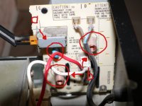
Included is a photo of a part of the Akai AM55 - For the moment I'm using its transformer to feed 2 UcD400's as my audio budget is recovering 😀
This part has a power switch, and some more parts. On top the mains comes in, the plugged wires go straight to the transformer primary.
I believe (a) is a kind of thermistor or am I wrong?
what are (b)? Are these resistors to do some kind of current limiting or is it something else? Is this "bad" ?
R on the (b) parts is 0.3 ohms
(a) did have some indications on it, but it became unreadable, sorry.
On the "output", voltage is identical to mains input, 230V AC
Thanks for the info,
Yves
Attachments
Yves,
A) A capacitor, used as a spark supressor for the mains switch.
B) Coils used as a mains filtering to avoid switch noises.
Leave these parts as-is, as they're there for a good reason, which is spark and noise supression from the switch.
Best regards,
Sander Sassen
http://www.hardwareanalysis.com
A) A capacitor, used as a spark supressor for the mains switch.
B) Coils used as a mains filtering to avoid switch noises.
Leave these parts as-is, as they're there for a good reason, which is spark and noise supression from the switch.
Best regards,
Sander Sassen
http://www.hardwareanalysis.com
OK thanks,
Can't thank you guys enough, I'm learning at geometrical rates here 😀
This is a fun way to learn things, from practical things to theoretical instead of the other way around...
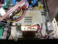
Does anyone have references on this transformer?
I'm afraid it's a custom job...
Secondary voltages are perfect for UcD's. I'm getting 55V DC on the caps.
Is it possible to "eyeball" the VA rating based on the size of this thing?
On the backplate of the Akai "220V 650W" is mentioned - but there are other secondaries on the transformer for the "pre" part of the integrated amp.
Can't thank you guys enough, I'm learning at geometrical rates here 😀
This is a fun way to learn things, from practical things to theoretical instead of the other way around...
Does anyone have references on this transformer?
I'm afraid it's a custom job...
Secondary voltages are perfect for UcD's. I'm getting 55V DC on the caps.
Is it possible to "eyeball" the VA rating based on the size of this thing?
On the backplate of the Akai "220V 650W" is mentioned - but there are other secondaries on the transformer for the "pre" part of the integrated amp.
Attachments
- Home
- Amplifiers
- Class D
- UcD400 Q & A