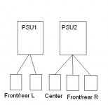
Well at least you'd go for an arrangement which is left/right symmetrical.FransDHT said:And this is the other one: Front and rear of one side to one supply and front/rear of the other side and center to the other supply:
1) The trivial case is one power supply for everything.
2) Front channels on one, remainder on the other.
3) Rear channels on one, remainder on the other.
I don't think there is much difference between 1, 2 and 3. A three-supply arrangement can make a difference: FL and RL have their own supply, the remainder shares the third.
Personally I wouldn't bother with intermediate arrangements. Either I'd have one supply for 5 channels or I'd have 5 mono blocks.
Bruno,
Since I will have two 500VA transformers and two sets of rectifier/BCC-cap (all supplied by Jan-Peter), will nickywicky's solution be the best? Will I need additional components for that solution?
How would that supply look in schematics?
Thanks for the help so far!
Frans
Since I will have two 500VA transformers and two sets of rectifier/BCC-cap (all supplied by Jan-Peter), will nickywicky's solution be the best? Will I need additional components for that solution?
How would that supply look in schematics?
Thanks for the help so far!
Frans
Since it is already decided you will be using two supplies, I'd go for one supply for left/right, an other for the two rears and center.FransDHT said:Bruno,
Since I will have two 500VA transformers and two sets of rectifier/BCC-cap (all supplied by Jan-Peter), will nickywicky's solution be the best? Will I need additional components for that solution?
Under the presumption that most of the power will be in the front channels this will give you the best reserve.
Hi, What exactly is Jan-Peter supplying in his powersupply kits?
Is it:
- 2x 10,000 caps
- single rectifier
- anything else?
Do these rectifiers benefit from bypassing with a small cap?
Would there be any benefit in a high end setup (using only a single transformer) from:
a) using two power supplies, one for each channel
b) using two rectifiers, one for each power rail
Thanks
Ewildgoose,
In the kit we have;
500VA toroidel transformer for 230V and 115V mains, gives 2x57VDC.
10.000uF / 63V BC Components capacitor (056 series, 2222.056.58103)
KBPC3502 bridge rectifier.
4x 100nF MKP capacitor.
Regards,
Jan-Peter
In the kit we have;
500VA toroidel transformer for 230V and 115V mains, gives 2x57VDC.
10.000uF / 63V BC Components capacitor (056 series, 2222.056.58103)
KBPC3502 bridge rectifier.
4x 100nF MKP capacitor.
Regards,
Jan-Peter
a: yes. The improvement in stereo imaging is clearly noticeable, and therefore worthwhileewildgoose said:
Would there be any benefit in a high end setup (using only a single transformer) from:
a) using two power supplies, one for each channel
b) using two rectifiers, one for each power rail
b: no, but. You can use lower voltage rectifiers, making the use of schottky diodes practical. If you're using non-schottky rectifiers, don't bother.
Hi,
Just returned from a visit to hypex to collect my 5 UcD400's and the power supplies. They were just testing the modules (nrs 049-053) so I had time for a chat. Very nice!
Jan-Peter suggested to use them balanced, but my pre-pro (Linn 5103) doesn't have a balanced output. He suggested to mak a cable with on one end XLR and on the other end RCA, with the - connected to ground at the RCA-side. What type of cable can I use for this? It needs at least 3 leads, can I for example connect the outer shielding to - at the XLR-side and to ground at the RCA-side?
Frans
You need only 2 leads, not 3. The third "lead", which connects pin 1 to ground, is the shield itself. Ask for "microphone cable" in an electronics store.FransDHT said:It needs at least 3 leads, can I for example connect the outer shielding to - at the XLR-side and to ground at the RCA-side?
Bruno,
OK, thats what I meant: using the shield as the third lead. Thanks.
Can I use any 'microphone' cable? Or can/should I use an audio interconnect cable?
Frans
OK, thats what I meant: using the shield as the third lead. Thanks.
Can I use any 'microphone' cable? Or can/should I use an audio interconnect cable?
Frans
Well a microphone cable is an audio cable isn't it?FransDHT said:Can I use any 'microphone' cable? Or can/should I use an audio interconnect cable?
Good microphone cable is a shielded twisted pair with added measures against acoustic noise pickup (such as cotton fillers or a supple semi-serve shield). Such cables perform better than many "audiophile" cables, which are often incorrectly built, resulting in noticeable colouration (subsequently marketed as "better sound").
If you buy it from maplins or the like then they usually also quote the capacitance. I would have thought that the more expensive stuff with lower capacitance was better in general?
Not a hard and fast rule but generally true.ewildgoose said:If you buy it from maplins or the like then they usually also quote the capacitance. I would have thought that the more expensive stuff with lower capacitance was better in general?
in my experience Prefer has some very decent balanced microphone cable. the the outer shield is *Very* thick and densely woven copper.
I'm currently using a diy cable, twisted silvered copper teflon insulated and shielded with the shield of a standard prefer microphone cable.
Sounds fine and it's fully BS-proof... 😉
http://www.prefer-ummels.com
I'm currently using a diy cable, twisted silvered copper teflon insulated and shielded with the shield of a standard prefer microphone cable.
Sounds fine and it's fully BS-proof... 😉
http://www.prefer-ummels.com
Jan-Peter,
Since some of us are not as lucky as FransDHT, to be able to visit the factory........how about some photographs of the assembly line and test area. I bet some of would like to know what goes on in the manufacturing process..................😉
Regards,
Jam (Still waiting for the UCD700/1000)
Since some of us are not as lucky as FransDHT, to be able to visit the factory........how about some photographs of the assembly line and test area. I bet some of would like to know what goes on in the manufacturing process..................😉
Regards,
Jam (Still waiting for the UCD700/1000)
Jam,
We have just moved to our new company building. Quit unpleasant to moving a complete company to a new location 😕
When we are complete settled I will show more photos on our website, www.hypex.nl . However you can see how the place looks 3 weeks ago......😉
I am also waiting till I get some time for the UcD700 (UcD1000). We already have some internal discussion for a 2KW UcD 😀
Regards,
Jan-Peter
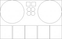
Well, I made a drawing of the box I have ordered to see how it all will fit in, but it is not very big. Inside measures are 23cm by 36cm by 7 cm.
The front and back are aluminium (4mm and 2.5mm) and the sides are cooling profiles. The size of the transformers is quite big (r=7cm), so there is little room to put the UcD400's.
Best would be if I could put them all at the back (or the front) panel, but would that be enough cooling? Will the heat flow to the cooling profiles?
The other option is to put two modules above each other on each side and one at the back. Will two above each other not result in heat problems?
I could get a bigger box at the same adress, but that would only be higher (3HE) and I don't want that. Or should I look for another box somewhere else, and get a deeper one? Where should I look (in the Netherlands) in that case?.
Frans

- Home
- Amplifiers
- Class D
- UcD400 Q & A