Hi,
You can try mounting Tx on a thick wood plate and avoid magnetic bolt/clamping system: non magnetic bolt plus wood plate on top or those thick plastic locking tapes whose exact name I don't know in English. Apart that, adding wood to the other metal walls can help damping vibrations.
I use thick wood plates as base on most of my ugly projects...
Good luck.
M
Hi, anyone can tell me what voltage is on the status leds on the board? Maybe 12V or something? Still did not instaled the PSU, and I am to change the leds, so I need this little information...
UCD400AD Version 6.1
Hello, I'm new to this diy hobby and with the help of a friend have managed to put together a stereo power amp based on the UCD400AD. Everything seems to be working ok.
I've been reading the threads on this forum and saw many recommendations of removing the input caps. My version has four caps very close to each other - C6, C7, C23 and C24.
I understand C23 and C24 are the input caps for the previous versions (?) but what are C6 and C7? Should they be removed as well.
Appreciate any advise.
And Another one for Jan-Peter
In much the same vain as the post above, I'm just putting together a pair of mono blocs built on the UcD400HG (V2 pcb) with HxR regulators.
Once I've played them "stock" for a while I'd like to try removing the input caps (I'm confident my pre-amp output is DC free and I'm implementing DC protection using the HG Mono power supply)
There have been many versions described and pictured through this lengthy thread to the extent that I'm now not at all sure which are the (OK to remove as long as I don't want warranty) Input oupling caps on my modules.
Any help (cap designation C23 etc type and value description of location , marked up picture) would be greatly appreciated.
I hope JP or Bruno sees this and can point me in the right direction.
Thanks in anticipation
Dave
Hi,
You can use a multimeter on "diode" function and trace the input path back and forth..."beeeep" means you find your cap 🙂
Cheers,
M
You can use a multimeter on "diode" function and trace the input path back and forth..."beeeep" means you find your cap 🙂
Cheers,
M
Hi Maxlorenz,
Thanks!
Doh ! Why didn't I think of that! Actually I guess I just wasn't thinking at all when I posted the question having got myself thouroughly confused by reading almost all of this thread in one session.
Cheers
Dave
Thanks!
Doh ! Why didn't I think of that! Actually I guess I just wasn't thinking at all when I posted the question having got myself thouroughly confused by reading almost all of this thread in one session.
Cheers
Dave
Dave,
Since I did not receive any replies on this forum, I went direct to Hypex who answered my question.
I'm not sure if you have the same version as I do but, just fyi, C6 and C7 should not be removed as these are the decoupling caps of the buffer op-amp.
Regards.
Since I did not receive any replies on this forum, I went direct to Hypex who answered my question.
I'm not sure if you have the same version as I do but, just fyi, C6 and C7 should not be removed as these are the decoupling caps of the buffer op-amp.
Regards.
Hi Dave,
You're welcome.
I recommend that you just solder a wire between cap leads instead of desoldering them (short). The holes used to be very little making difficult finding a suitable wire.
You're welcome.
I recommend that you just solder a wire between cap leads instead of desoldering them (short). The holes used to be very little making difficult finding a suitable wire.
I am building a balanced DAC aiming to connect it to my two UCD400AD (have the modules but not built yet).
My plan is balanced DAC => volumn control => UCD400.
However my DAC, without coupling cap, will have 3V to 4V dc offset. Is it safe to connect as above without any coupling cap?
My plan is balanced DAC => volumn control => UCD400.
However my DAC, without coupling cap, will have 3V to 4V dc offset. Is it safe to connect as above without any coupling cap?
annton said:However my DAC, without coupling cap, will have 3V to 4V dc offset. Is it safe to connect as above without any coupling cap?
No, that's way too high. A maximum of 10mV was recommended to me by Hypex.
annton said:Even for my DAC with balanced output?
The Hypex UcD amps are instrumentation amplifiers, so as long as you have the same voltage on both balanced outputs you should be fine. Using a balanced source is actually the most desirable way to drive the UcD amps.
BWRX said:
The Hypex UcD amps are instrumentation amplifiers, so as long as you have the same voltage on both balanced outputs you should be fine. Using a balanced source is actually the most desirable way to drive the UcD amps.
thx 🙂
HG UCD 400 too hot?
Just finished the amp, sounds great but the modules get a bit hot. I've got vents in the case and its not so hot that I can't touch it. Trouble is I've got no referance, my MF A3 was a standard A-B amp and this one is about the same temperature wise. I'm using a pair of active PSU's running at 59v. I'll see how ist seltels down over the next few days.
Just finished the amp, sounds great but the modules get a bit hot. I've got vents in the case and its not so hot that I can't touch it. Trouble is I've got no referance, my MF A3 was a standard A-B amp and this one is about the same temperature wise. I'm using a pair of active PSU's running at 59v. I'll see how ist seltels down over the next few days.
Attachments
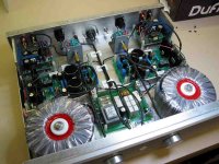
Hi Deckman,
Very nice construction!
It's normal that you have any heat losses. For a Class-D amp the Idle losess are 1-1,5% of maximum power. With a UcD400, this is +/- 6W, the regulator of FET driver circuit is also on board and this will create an extra heat dissipation of +/2W.
Don't forget that your amplifier is capable of 2x 400W clean output power.... 😉
Regards,
Jan-Peter
I understand UcD400 in idle will have higher losses (and then be noticeably hotter) than UcD180 in idle. But I'd like to understand what differences in losses one might expect while the amps are working outputting the same power.
Sorry if my question isn't too clear, I new to DIY hifi.
Sorry if my question isn't too clear, I new to DIY hifi.
Hi there!
I ordered 2 UcD400 amps with 1x supply HG and 1 x TR700 trafo, according to the site this should be enough to power the 2 amps.
Is this the case or should i maybe order annother supply HG and trafo?
I was also thinking of adding extra caps to the PSU, it looks like it's using 4 x 10.000uf right now.
I was thinking of adding another 4 x 10.000uf caps, will this make any change or is the 4x 10.000 enough? If you have 2 supply HG boards you have 8x 10.000uf in total so actually the same as i want it to be.
BTW, this is the case it will be build in with just a nice powerswitch (about the same as on the hypex site but then 5 times as cheap)
An externally hosted image should be here but it was not working when we last tested it.
BTW, i ordered a TR400 instead of a TR700 but i asked Hypex to change it to a TR501 trafo for a bit more current.
UCD 400 gain, what size R3?
I want to reduce the gain on my UCD 400. (About 8-10 dB) I'm currently attenuating the signal before it reaches the amplifier but I understand I can do this by changing the value of resistor R3.
However having read the article by Bruno on reducing gain I'm still unclear as to whether this is a better way?
Assuming that it is, Can anyone please tell me what size and type of resistor is used, I'm not too familiar with SMT (and even on a good day with a clean pair of specs and a magnifying glass, its still hard to see the damm things) I can get someone to do this for me as long as I provide the components. I think a value of 2k should be about right.
- Home
- Amplifiers
- Class D
- UcD400 Q & A