Hello all,
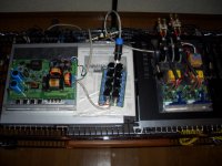
I finally did it, connected my heavily modified K6 SMPS (see other thread) to two UcD400 modules. Look at the setup in the attached picture. Yes, it is extremely experimental and no kids allowed in its neighborhood. Of course this is going to be build in in a case in the future. On the left is the SMPS, in the mid the added caps in RCR configuration 4x parallel per rail with R=0.1Ohm and C=8200uF. On the right are the two UcD400s with an additional Elna Cerafine 10.000uF per rail for the final touch. The yellow polyprop caps are not coupling caps but are part of the 6dB roll-off filter to compensate my dipole woofers 6dB roll-of towards lower frequencies.
Next to the Elna's you can see a small board with 5 3W resistors (4x3.3k and 1 4.7k) forming a resistor of 700 Ohm. This resistor is placed from + rail to GND to pull extra current from the + rail to GND. Without this resistor, the SMPS suffers from power supply pumping as the - rail of the UcD modules draws more current than the + rail. In that case, the + rail goes to about 65V while the - rail goes to 55V. With these resistors, the + and - rail both go to about 58.5V. So these resistors are needed (burning a bit extra power), and I need more of them when I connect more modules to the supply.
The two UcDs were driving a total of 4 woofers, each channel 2 woofers in parallel giving a 4 ohm load per channel. To avoid power supply pumping, I reversed the polarity of the left channel and connected the speakers of the left channel in such a way that both left and right woofers are in phase.
In the final system, I want to use two UcD400s for each channel in either a bridge configuration or both modules out of phase (as in bridge) but each woofer one amp, so each amp would see only a 8 Ohm load.
So the current case were 4 woofers are fed from one SMPS is much worse than the final situation were one SMPS feeds two woofers and two amps for mid and high that don't need much power.
See subsequent posts with some measurements
Best regards
Gertjan
Attachments
ghemink said:
See subsequent posts with some measurements
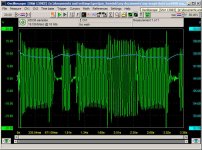
Then I put in a CD with lots of bass to test the setup with the woofers connected, no dummy resistors, real speakers.
Since the woofers are dipoles, the amps have to deliver much more voltage at low frequencies to get the same SPL. I used track 5 of "Stonehenge 4" from"Hatfield's End". This track has some pretty heavy synthesized bass at very low frequencies at high SPL. This is good to give your woofers a good workout.
I connected channel 1 of the scope to the right channel output and channel 2 to the + power rail. So I wanted to monitor the output voltage fom the UcD and the rail voltage at the same time while driving the while thing with high SPL LF material.
Attached is a picture of a short sample of that track. You can see the amplitude of the signal almost hitting 20V. The blue line is the rail voltage which is about 58V with a scale of 1V per division to be able to see it moving 🙂. I can assure you, it was getting very loud in my small room, even with these dipoles that have low efficiency at low frequencies. You can see the effect of the SMPS slowly regulating the rail voltage. I made the feedback loop of the SMPS very slow so that it regulates much slower than the lowest LF that I would ever pump in the system.
Note that the peak to peak rail voltage variation in this particular measurement was only 0.8V!! Very good I think.
More to come.
Attachments
Re: Re: UcD400 + modified K6 SMPS works great
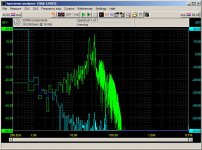
And this is the FFT of the previous sample (at least a large part of it).
Note that the scales are going from 20dBV to -60dBV. -60dBV corresponds with 1mV peak voltage (or about 0.7mV RMS) for both the signal going to the speaker and the + rail.
You can see that there were two main frequency components in the signal around 26Hz and 35Hz.
On the + rail (the blue line) this resulted in some low frequency content between 1 and 10Hz (rolling off with about 6dB/Oct). This is the SMPS doing its regulation at these low frequencies as could be seen on the previous picture. Then it can be seen that the + rail has also two small peaks at around 26 and 35Hz and two at around 52Hz and at 70Hz. These are all expected and correlate with the output signal of the amp. There is no sign of any mains related hum at 100Hz, vey nice. The signals on the + rail are about 60dB or more below the level of the output signal of the amp. I would say that this is very good. I don't think there are many conventional supplies that can do this, especially, the undetectable low level of the 100Hz mains related can not easily be beaten by a conventional supply.
Cheers
Gertjan
ghemink said:
More to come.
And this is the FFT of the previous sample (at least a large part of it).
Note that the scales are going from 20dBV to -60dBV. -60dBV corresponds with 1mV peak voltage (or about 0.7mV RMS) for both the signal going to the speaker and the + rail.
You can see that there were two main frequency components in the signal around 26Hz and 35Hz.
On the + rail (the blue line) this resulted in some low frequency content between 1 and 10Hz (rolling off with about 6dB/Oct). This is the SMPS doing its regulation at these low frequencies as could be seen on the previous picture. Then it can be seen that the + rail has also two small peaks at around 26 and 35Hz and two at around 52Hz and at 70Hz. These are all expected and correlate with the output signal of the amp. There is no sign of any mains related hum at 100Hz, vey nice. The signals on the + rail are about 60dB or more below the level of the output signal of the amp. I would say that this is very good. I don't think there are many conventional supplies that can do this, especially, the undetectable low level of the 100Hz mains related can not easily be beaten by a conventional supply.
Cheers
Gertjan
Attachments
New system tests
Gertjan
Ambitious project! Good job.
I was wondering why you limited the bandwidth of the SMPS to make it respond so slowly. I am doing a similar project and would expect much better regulation with wider bandwidth. I think the buffer caps are necessary for decent sonics and plan on using them as well. Wondered why you didn’t use some inductors instead of .1 ohm res for filtering. I am a little surprised at the pumping issue with all the buffering. But thanks for that info, I will watch for it.
Do all those resistors run hot, wouldn’t want to see you cook your caps. The Speakon connector is a nice touch but wondered why you used it? Will the power supply be in a separate case? If I didn’t see the console those connectors alone would tell me you are in pro sound. It is nice to see someone in the pro field really serious about sonics.
Try using the Powercon for your power input connector, they are an ugly color but functionally superior. I have totally switched over to them for all my own stuff. The only thing I have observed about them is that you must resist the urge to twist them for a power switch. The inrush current will arc them and destroy the contacts. Only connect them to equipment that is turned off and they will last a very long time.
Roger
Re: New system tests
Hi Roger,
Thanks for your interest in my project. A few answers:
Actually the bandwith of the SMPS feedback loop is not limited to such low frequencies. The feedback loop has a constant gain between 1Hz up to about 1500Hz. After 1500Hz it drops off with 6dB/Oct and below 1Hz, it goes up with 6dB/Oct (integrator). Because of all the caps, at high frequencies, the output impedance of the supply is determined by the output caps. At low frequencies to a certain extent by the caps and by the feedback loop. So it is not only dependent on the caps. Actually the gain of the feedback loop is more than a factor 6 in the flat area and the gain of the SMPS itself (after the voltage divider for the voltage feedback) is about a factor 2 or so. So total gain is more than a factor 10. This keeps the mains related ripple voltage very low.
On the SMPS there are two filter inductors for each rail. They are 350uH, so quite large value. I did not add additional ones to keep the transfer function of the output filter simple.
The 0.1 ohm resistors don't get hot as this is for home audio, the modules are not running constantly at high power levels. Besides that, the resistors are 3W types and are actually 0.2 Ohm, 2 of them in parrallel and 4 of those RCR filters in parrallel. So even if I would draw say 10A continuosly, each resistor would conduct only 1.25A with a voltage drop of 0.25V which is only 0.3W dissipation. Of course in general I will be far below that current level.
In fact, I could have used 0.1 Ohm 1W resistors but I had a large amount of 0.2 Ohm 3W resistors at home.
I used the speakon for the power conection. Initially I was planning to put the SMPS in a seperate case. However, I maybe able to put the amps and SMPS in the same case. Then I won't need that connector. Also for this setup, it is easier to move around the SMPS and amp seperately when hacking it 🙂
I'm not in the pro-audio business, I'm working for a company that is (hopefully) making the memory cards that you use in your digital camera (SanDisk). If I would be in the pro-audio business I would want to be serious about sonics, however, budget limitations would probably not allow that so I'm not good for that business:-(
Thanks for the tip on the powercon. I'll see what I use. However, since it is for home use, in the end, not a lot of plugging/unplugging is needed, so maybe I go conventional.
Thanks and best regards
Gertjan
sx881663 said:Gertjan
Ambitious project! Good job.
I was wondering why you limited the bandwidth of the SMPS to make it respond so slowly. I am doing a similar project and would expect much better regulation with wider bandwidth. I think the buffer caps are necessary for decent sonics and plan on using them as well. Wondered why you didn’t use some inductors instead of .1 ohm res for filtering. I am a little surprised at the pumping issue with all the buffering. But thanks for that info, I will watch for it.
Do all those resistors run hot, wouldn’t want to see you cook your caps. The Speakon connector is a nice touch but wondered why you used it? Will the power supply be in a separate case? If I didn’t see the console those connectors alone would tell me you are in pro sound. It is nice to see someone in the pro field really serious about sonics.
Try using the Powercon for your power input connector, they are an ugly color but functionally superior. I have totally switched over to them for all my own stuff. The only thing I have observed about them is that you must resist the urge to twist them for a power switch. The inrush current will arc them and destroy the contacts. Only connect them to equipment that is turned off and they will last a very long time.
Roger
Hi Roger,
Thanks for your interest in my project. A few answers:
Actually the bandwith of the SMPS feedback loop is not limited to such low frequencies. The feedback loop has a constant gain between 1Hz up to about 1500Hz. After 1500Hz it drops off with 6dB/Oct and below 1Hz, it goes up with 6dB/Oct (integrator). Because of all the caps, at high frequencies, the output impedance of the supply is determined by the output caps. At low frequencies to a certain extent by the caps and by the feedback loop. So it is not only dependent on the caps. Actually the gain of the feedback loop is more than a factor 6 in the flat area and the gain of the SMPS itself (after the voltage divider for the voltage feedback) is about a factor 2 or so. So total gain is more than a factor 10. This keeps the mains related ripple voltage very low.
On the SMPS there are two filter inductors for each rail. They are 350uH, so quite large value. I did not add additional ones to keep the transfer function of the output filter simple.
The 0.1 ohm resistors don't get hot as this is for home audio, the modules are not running constantly at high power levels. Besides that, the resistors are 3W types and are actually 0.2 Ohm, 2 of them in parrallel and 4 of those RCR filters in parrallel. So even if I would draw say 10A continuosly, each resistor would conduct only 1.25A with a voltage drop of 0.25V which is only 0.3W dissipation. Of course in general I will be far below that current level.
In fact, I could have used 0.1 Ohm 1W resistors but I had a large amount of 0.2 Ohm 3W resistors at home.
I used the speakon for the power conection. Initially I was planning to put the SMPS in a seperate case. However, I maybe able to put the amps and SMPS in the same case. Then I won't need that connector. Also for this setup, it is easier to move around the SMPS and amp seperately when hacking it 🙂
I'm not in the pro-audio business, I'm working for a company that is (hopefully) making the memory cards that you use in your digital camera (SanDisk). If I would be in the pro-audio business I would want to be serious about sonics, however, budget limitations would probably not allow that so I'm not good for that business:-(
Thanks for the tip on the powercon. I'll see what I use. However, since it is for home use, in the end, not a lot of plugging/unplugging is needed, so maybe I go conventional.
Thanks and best regards
Gertjan
Re: Re: New system tests
ABout the power supply pumping. As the output resistance of the SMPS is quite high at those low currents. The imbalance in + and - rail current (DC current) is enough to cause this big difference between + and - rail. However, with the resistive additional load, it is no issue. I added all those caps to prevent power supply pumping in case of low frequency signals. But for the woofers I will use a bridged solution anyway. the midwoofers start from about 140Hz, these will be fed by a single amp but that should be no issue with all these caps. In fact, I want to give each amp its own caps that are all decoupled with RCR like parallel caps. This to decouple the supplies for woofer amps, midwoofer amp and tweeter amp. For midwoofer and tweeter I'm thinking of two 8200uF caps per rail and topping it off again with elna cerafines. Sure this stuff would be too expensive for pro-audio🙂
Best regards
Gertjan
ghemink said:
Hi Roger,
Thanks for your interest in my project. A few answers:
Actually the bandwith of the SMPS feedback loop is not limited to such low frequencies. The feedback loop has a constant gain between 1Hz up to about 1500Hz. After 1500Hz it drops off with 6dB/Oct and below 1Hz, it goes up with 6dB/Oct (integrator). Because of all the caps, at high frequencies, the output impedance of the supply is determined by the output caps. At low frequencies to a certain extent by the caps and by the feedback loop. So it is not only dependent on the caps. Actually the gain of the feedback loop is more than a factor 6 in the flat area and the gain of the SMPS itself (after the voltage divider for the voltage feedback) is about a factor 2 or so. So total gain is more than a factor 10. This keeps the mains related ripple voltage very low.
On the SMPS there are two filter inductors for each rail. They are 350uH, so quite large value. I did not add additional ones to keep the transfer function of the output filter simple.
The 0.1 ohm resistors don't get hot as this is for home audio, the modules are not running constantly at high power levels. Besides that, the resistors are 3W types and are actually 0.2 Ohm, 2 of them in parrallel and 4 of those RCR filters in parrallel. So even if I would draw say 10A continuosly, each resistor would conduct only 1.25A with a voltage drop of 0.25V which is only 0.3W dissipation. Of course in general I will be far below that current level.
In fact, I could have used 0.1 Ohm 1W resistors but I had a large amount of 0.2 Ohm 3W resistors at home.
I used the speakon for the power conection. Initially I was planning to put the SMPS in a seperate case. However, I maybe able to put the amps and SMPS in the same case. Then I won't need that connector. Also for this setup, it is easier to move around the SMPS and amp seperately when hacking it 🙂
I'm not in the pro-audio business, I'm working for a company that is (hopefully) making the memory cards that you use in your digital camera (SanDisk). If I would be in the pro-audio business I would want to be serious about sonics, however, budget limitations would probably not allow that so I'm not good for that business:-(
Thanks for the tip on the powercon. I'll see what I use. However, since it is for home use, in the end, not a lot of plugging/unplugging is needed, so maybe I go conventional.
Thanks and best regards
Gertjan
ABout the power supply pumping. As the output resistance of the SMPS is quite high at those low currents. The imbalance in + and - rail current (DC current) is enough to cause this big difference between + and - rail. However, with the resistive additional load, it is no issue. I added all those caps to prevent power supply pumping in case of low frequency signals. But for the woofers I will use a bridged solution anyway. the midwoofers start from about 140Hz, these will be fed by a single amp but that should be no issue with all these caps. In fact, I want to give each amp its own caps that are all decoupled with RCR like parallel caps. This to decouple the supplies for woofer amps, midwoofer amp and tweeter amp. For midwoofer and tweeter I'm thinking of two 8200uF caps per rail and topping it off again with elna cerafines. Sure this stuff would be too expensive for pro-audio🙂
Best regards
Gertjan
Re: Re: Re: New system tests
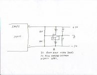
About the supply pumping issue, this is really not a pumping issue but a problem with the design of the supply. I realized something like this could happen with this type of design no matter how well regulated. You can’t control 2 voltages with one loop. In fact probably better to only control one and let the other do as it will. At least one will be right. A different way to do it would be to generate one voltage of around 140 volts going to 2 series connected caps with an active ground point generator controlling the mid point. (See drawing for idea) Extra parts but not as bad as my current solution. My not so simple solution is to use 2 supplies. This does solve the problem but costs too much. You could do something like some of the Victor circuits where you have a PFC AC/DC front-end followed by 2 separate DC/DC modules with independent regulation. This would be a nice solution but I can’t afford it. Other ideas welcome. Very much would like to see an elegant, reasonably priced solution to powering these modules, one without heavy bulky transformers.
Btw, the resistors I was referring to, I think, are the 700 ohm ones you made up. These would generate some heat. Seems this could be enough to cause a problem if you don’t have good ventilation.
As you know big caps have significant ESL that limits their effectiveness at higher frequencies. A solution is to bypass them with something like .1uf and to break the chain with inductors of something like 100uh on both legs. They could be placed between as few as 2 caps. This could be very beneficial as a good inductor would be in the millohm range to dc but around 600 ohms at 1MHz. Breaking a direct AC hf path from the PS ground could be worth doing.
Here I am talking like an authority and I haven’t tried most of this for myself. I will post results as I get them. I have the new UcD400’s but am lacking the rest of the parts.
Roger
ghemink said:
ABout the power supply pumping. As the output resistance of the SMPS is quite high at those low currents. The imbalance in + and - rail current (DC current) is enough to cause this big difference between + and - rail. However, with the resistive additional load, it is no issue. I added all those caps to prevent power supply pumping in case of low frequency signals. But for the woofers I will use a bridged solution anyway. the midwoofers start from about 140Hz, these will be fed by a single amp but that should be no issue with all these caps. In fact, I want to give each amp its own caps that are all decoupled with RCR like parallel caps. This to decouple the supplies for woofer amps, midwoofer amp and tweeter amp. For midwoofer and tweeter I'm thinking of two 8200uF caps per rail and topping it off again with elna cerafines. Sure this stuff would be too expensive for pro-audio🙂
Best regards
Gertjan
About the supply pumping issue, this is really not a pumping issue but a problem with the design of the supply. I realized something like this could happen with this type of design no matter how well regulated. You can’t control 2 voltages with one loop. In fact probably better to only control one and let the other do as it will. At least one will be right. A different way to do it would be to generate one voltage of around 140 volts going to 2 series connected caps with an active ground point generator controlling the mid point. (See drawing for idea) Extra parts but not as bad as my current solution. My not so simple solution is to use 2 supplies. This does solve the problem but costs too much. You could do something like some of the Victor circuits where you have a PFC AC/DC front-end followed by 2 separate DC/DC modules with independent regulation. This would be a nice solution but I can’t afford it. Other ideas welcome. Very much would like to see an elegant, reasonably priced solution to powering these modules, one without heavy bulky transformers.
Btw, the resistors I was referring to, I think, are the 700 ohm ones you made up. These would generate some heat. Seems this could be enough to cause a problem if you don’t have good ventilation.
As you know big caps have significant ESL that limits their effectiveness at higher frequencies. A solution is to bypass them with something like .1uf and to break the chain with inductors of something like 100uh on both legs. They could be placed between as few as 2 caps. This could be very beneficial as a good inductor would be in the millohm range to dc but around 600 ohms at 1MHz. Breaking a direct AC hf path from the PS ground could be worth doing.
Here I am talking like an authority and I haven’t tried most of this for myself. I will post results as I get them. I have the new UcD400’s but am lacking the rest of the parts.
Roger
Attachments
Originally posted by sx881663
As you know big caps have significant ESL that limits their effectiveness at higher frequencies. A solution is to bypass them with something like .1uf and to break the chain with inductors of something like 100uh on both legs.
Hi,
nowadays this is more urban legend than anything else. Large caps use several parallel connections to the foil windings. If you do some search, you will find that inductance is largely independant of size. Epcos is one manufacturer that specifies ESL for all their electrolytics. Over various series and sizes ESL differs from 10nH to 20nH. It is indicative that low ESL (13nH) versions are available only in cans with diameter larger than 60mm. I would agree though that connections to large cans can be more inductive, but only if you use point to point wiring.
Best regards,
Jaka Racman
Jaka Racman said:
Hi,
nowadays this is more urban legend than anything else. Large caps use several parallel connections to the foil windings. If you do some search, you will find that inductance is largely independant of size. Epcos is one manufacturer that specifies ESL for all their electrolytics. Over various series and sizes ESL differs from 10nH to 20nH. It is indicative that low ESL (13nH) versions are available only in cans with diameter larger than 60mm. I would agree though that connections to large cans can be more inductive, but only if you use point to point wiring.
Best regards,
Jaka Racman
I defer to your superior knowledge. I have not taken apart any caps larger than about 55mm. All of them I did had single lead connections. I don’t remember all the vendors but at the time they all had reasonably low ESR. This was my 4th qualifying parameter. (Voltage, size, value, ripple current and cost) (As all the caps I was qualifying had the same basic size and were 105 deg units ripple current was pretty much an ESR measurement.) I don’t understand how large cans can have such high ESR if they are using multiple connections. I can see why ESL is not the primary self resonate factor but the cap value its self would be.
I don’t think I have ever seem a published ESL value and always went by the self resonate value to judge merit. It would be very nice if ESL values were listed by all vendors.
The Jensen multipole units are a whole different animal however. Too bad they are just way too expensive to consider. Have you looked at them? Rather interesting app notes.
Thank you for your input.
Roger
Re: Re: Re: Re: New system tests
Hi Roger,
yes, I agree, it is not really power supply pumping, it looks a bit like it and it is caused by the way the feedback is done.
I don't want to take the feedback from only one rail is this will also result in an asymmetric behavior.
I also briefly considered a suggestion as yours by making a kind of active GND connection. However, this increases complexity and I don't like the idea of an active GND, I prefer the GND to be more or less solid.
I have also been thinking of making a small active circuit with a voltage divider between + and - rail that is compared with GND level and drives a couple of transistors that actively pull current from the line that has the highest voltage level. This is also active so I don't really want to do it. Then I first checked the resistor method that I use now and it works very well, exact mathing of the + and - rail current is not needed, if you are close enough, it works.
I also considered using an SMPS for each rail. This is the best method of course, also the most expensive method and then the thing would be come too big to fit in a case together with the amps. If I would go for that method, i would feed both left and right chanel amps from the same supplies with the supplies in a sperate case. However, the resistor method seems to work good enough, and yes, it burns some power but they are not getting that hot.
I don't think the caps have that much ESL, I have tested this by applying a square wave current to them and measuring the voltage over the caps. This allows me to see the ESR value. By putting a 100nF cap over the elcaps I can see if there are any resonance effects. And yes, they resonate at a few Mhz (ringing when the current direction changes). So for that reason, I don't want to put 0.1uF caps in parallel with the elcaps.
To isolate the amps from the SMPS I"m now using this virtual 4-pole with parallel RCR networks. I plan to extend this in the final version to also using Rs in the GND connection so that also the GND conection from SMPS and amps are seperated. And also each amp can get its own isolated GND connection. As I work with XLR inputs, that should be OK.
I don't want to use any inductors as that will give in combination with the caps some resonant behavior, depending on Q-factor of course. There are already inductors in the SMPS but they are in the feedback loop and I made the Q-factor of that output filter very low with those big caps and by using the RCR like setup. This results in very well defined behavior of the SMPS as you can see in some other hread.
best regards
Gertjan
sx881663 said:
About the supply pumping issue, this is really not a pumping issue but a problem with the design of the supply. I realized something like this could happen with this type of design no matter how well regulated. You can’t control 2 voltages with one loop. In fact probably better to only control one and let the other do as it will. At least one will be right. A different way to do it would be to generate one voltage of around 140 volts going to 2 series connected caps with an active ground point generator controlling the mid point. (See drawing for idea) Extra parts but not as bad as my current solution. My not so simple solution is to use 2 supplies. This does solve the problem but costs too much. You could do something like some of the Victor circuits where you have a PFC AC/DC front-end followed by 2 separate DC/DC modules with independent regulation. This would be a nice solution but I can’t afford it. Other ideas welcome. Very much would like to see an elegant, reasonably priced solution to powering these modules, one without heavy bulky transformers.
Btw, the resistors I was referring to, I think, are the 700 ohm ones you made up. These would generate some heat. Seems this could be enough to cause a problem if you don’t have good ventilation.
As you know big caps have significant ESL that limits their effectiveness at higher frequencies. A solution is to bypass them with something like .1uf and to break the chain with inductors of something like 100uh on both legs. They could be placed between as few as 2 caps. This could be very beneficial as a good inductor would be in the millohm range to dc but around 600 ohms at 1MHz. Breaking a direct AC hf path from the PS ground could be worth doing.
Here I am talking like an authority and I haven’t tried most of this for myself. I will post results as I get them. I have the new UcD400’s but am lacking the rest of the parts.
Roger
Hi Roger,
yes, I agree, it is not really power supply pumping, it looks a bit like it and it is caused by the way the feedback is done.
I don't want to take the feedback from only one rail is this will also result in an asymmetric behavior.
I also briefly considered a suggestion as yours by making a kind of active GND connection. However, this increases complexity and I don't like the idea of an active GND, I prefer the GND to be more or less solid.
I have also been thinking of making a small active circuit with a voltage divider between + and - rail that is compared with GND level and drives a couple of transistors that actively pull current from the line that has the highest voltage level. This is also active so I don't really want to do it. Then I first checked the resistor method that I use now and it works very well, exact mathing of the + and - rail current is not needed, if you are close enough, it works.
I also considered using an SMPS for each rail. This is the best method of course, also the most expensive method and then the thing would be come too big to fit in a case together with the amps. If I would go for that method, i would feed both left and right chanel amps from the same supplies with the supplies in a sperate case. However, the resistor method seems to work good enough, and yes, it burns some power but they are not getting that hot.
I don't think the caps have that much ESL, I have tested this by applying a square wave current to them and measuring the voltage over the caps. This allows me to see the ESR value. By putting a 100nF cap over the elcaps I can see if there are any resonance effects. And yes, they resonate at a few Mhz (ringing when the current direction changes). So for that reason, I don't want to put 0.1uF caps in parallel with the elcaps.
To isolate the amps from the SMPS I"m now using this virtual 4-pole with parallel RCR networks. I plan to extend this in the final version to also using Rs in the GND connection so that also the GND conection from SMPS and amps are seperated. And also each amp can get its own isolated GND connection. As I work with XLR inputs, that should be OK.
I don't want to use any inductors as that will give in combination with the caps some resonant behavior, depending on Q-factor of course. There are already inductors in the SMPS but they are in the feedback loop and I made the Q-factor of that output filter very low with those big caps and by using the RCR like setup. This results in very well defined behavior of the SMPS as you can see in some other hread.
best regards
Gertjan
Power supply observations
Gertjan
I have done quite a bit of LF (audio and below) analog design and have done a little with DC/DC converter design as well. I am not comfortable with all this HF stuff yet. It has been a long time since I have had to deal with HF resonance issues like this. This is why I am being very conservative, for now, with my own stuff. I defer to your greater experience and appreciate your insights.
Concerning inductors, this is another bag of worms as they all have lots of non ideal behavior and must be selected with care. It would be nice if you could trust the specs. It would also be nice if the specs showed behavior at differing currents and temperatures. I find them much more difficult to sort out than caps.
Roger
Hi,
Gertjan, I'm glad this project has worked out so well for you, you've certainly put the effort into it and deserve as much.
Roger, I've been enjoying your posts a great deal, nice to have your participation around here.
Regards,
Chris
Gertjan, I'm glad this project has worked out so well for you, you've certainly put the effort into it and deserve as much.
Roger, I've been enjoying your posts a great deal, nice to have your participation around here.
Regards,
Chris
classd4sure said:Hi,
Gertjan, I'm glad this project has worked out so well for you, you've certainly put the effort into it and deserve as much.
Roger, I've been enjoying your posts a great deal, nice to have your participation around here.
Regards,
Chris
That praise means a lot, thanks. I have often wondered if I was wasting my time. I do enjoy sharing my knowledge and trying to help. I also have learned a lot from the forum and the many knowledgeable people posting here.
Roger
classd4sure said:Hi,
Gertjan, I'm glad this project has worked out so well for you, you've certainly put the effort into it and deserve as much.
Roger, I've been enjoying your posts a great deal, nice to have your participation around here.
Regards,
Chris
Hi Chris,
Thanks, it was fun to do, it took quite a bit of time since most of it had to be done late in the evening. Probably the same problem as most of us have here. Most important is that I`m quite happy with the results, but as always will keep on improving but first need to get some cases and build up the other one as well. I have a total of 8 UcD modules that need to be powered, now I use only two of them.
Best regards
Gertjan
- Status
- Not open for further replies.
- Home
- Amplifiers
- Class D
- UcD400 + modified K6 SMPS works great